Hello, and welcome back to Beyond NERVA! Today’s blog post is a special one, spurred on by the announcement recently about the Transport and Energy Module, Russia’s new nuclear electric space tug! Because of the extra post, the next post on liquid fueled NTRs will come out on Monday or Tuesday next week.
This is a fascinating system with a lot of promise, but has also gone through major changes in the last year that seem to have delayed the program. However, once it’s flight certified (which is to be in the 2030s), Roscosmos is planning on mass-producing the spacecraft for a variety of missions, including cislunar transport services and interplanetary mission power and propulsion.
Begun in 2009, the TEM is being developed by Energia on the spacecraft side and the Keldysh Center on the reactor side. This 1 MWe (4MWt) nuclear reactor will power a number of gridded ion engines for high-isp missions over the spacecraft’s expected 10-year mission life.
First publicly revealed in 2013 at the MAKS aerospace show, a new model last year showed significant changes, with additional reporting coming out in the last week indicating that more changes are on the horizon (there’s a section below on the current TEM status).
This is a rundown of the TEM, and its YaDEU reactor. I also did a longer analysis of the history of the TEM on my Patreon page (patreon.com/beyondnerva), including a year-by-year analysis of the developments and design changes. Consider becoming a Patron for only $1 a month for additional content like early blog access, extra blog posts and visuals, and more!
The TEM is a nuclear electric spacecraft, designed around a gas-cooled high temperature reactor and a cluster of ion engines.
The TEM is designed to be delivered by either Proton or Angara rockets, although with the retirement of the Proton the only available launcher for it currently is the Angara-5.
Secondary Power System
Both versions of the TEM have had secondary folding photovoltaic power arrays. Solar panels are relatively commonly used for what’s known as “hotel load,” or the load used by instrumentation, sensors, and other, non-propulsion systems.
It is unclear if these feed into the common electrical bus of the spacecraft or form a secondary system. Both schemes are possible; if the power is run through a common electrical bus the system is simpler, but a second power distribution bus allows for greater redundancy in the spacecraft.
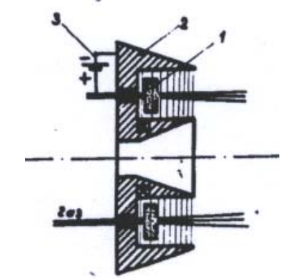
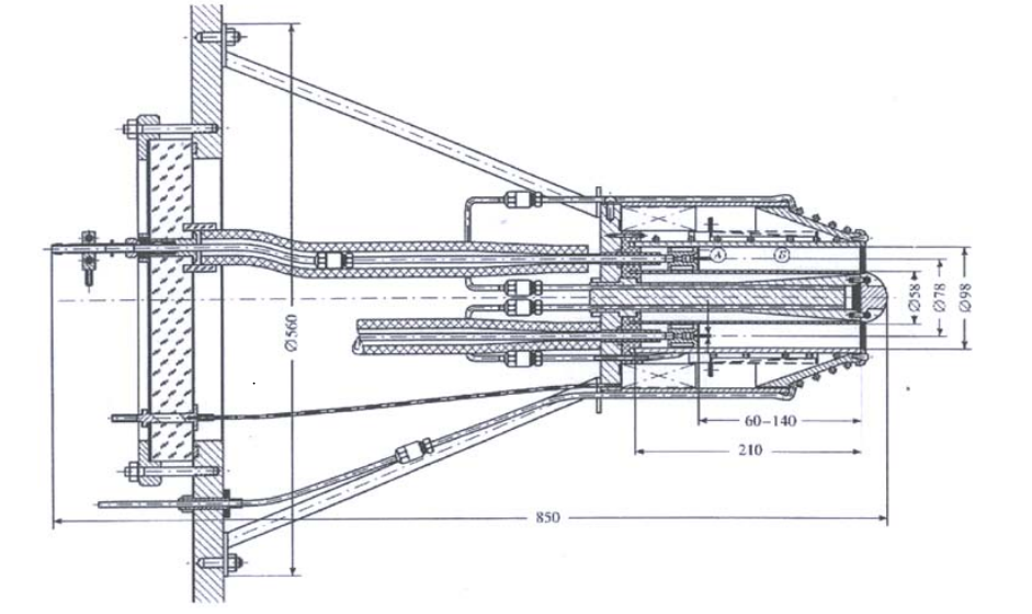
The ID-500 was designed by the Keldysh Center specifically to be used on the TEM, in conjunction with YaEDU. Due to the very high power availability of the YaEDU, standard ion engines simply weren’t able to handle either the power input or the needed propellant flow rates, so a new design had to be come up with.
The ID-500 is a xenon-propelled ion engine, with each thruster having a maximum power level of about 35 kW, with a grid diameter of 500 mm. The initially tested design in 2014 (see references below) had a tungsten cathode, with an expected lifetime of 5000 hours, although additional improvements through the use of a carbon-carbon cathode were proposed which could increase the lifetime by a factor of 10 (more than 50,000 hours of operation).
Each ID-500 is designed to throttle from 375-750 mN of thrust, varying both propellant flow rate and ionization chamber pressure. The projected exhaust velocity of the engine is 70,000 m/s (7000 s isp), making it an attractive option for the types of orbit-altering, long duration missions that the TEM is expected to undertake.
The fact that this system uses a gridded ion thruster, rather than a Hall effect thruster (HET), is interesting, since HETs are the area that Soviet, then Russian, engineers and scientists have excelled at. The higher isp makes sense for a long-term tug, but with a system that seems that it could refuel, the isp-to-thrust trade-off is an interesting decision.
The initial design released at MAKS 2013 had a total of 16 ion thrusters on four foldable arms, but the latest version from MAKS-2019 has only five thrusters. The new design is visible below:
The first design is ideal for the tug configuration: the distance between the thrusters and the payload ensure that a minimal amount of the propellant hits the payload, robbing the spacecraft of thrust, contaminating the spacecraft, and possibly building up a skin charge on the payload. The downside is that those arms, and their hinge system, cost mass and complexity.
The new design clusters only five (less than one third) thrusters clustered in the center-line of the spacecraft. This saves mass, but the decrease in the number of thrusters, and the fact that they’re placed in the exact location that the payload makes most sense to attach, has me curious about what the mission profile for this initial TEM is.
It is unclear if the thrusters are the same design.
This may be the most interesting thing in in the TEM: the heat rejection system.
Most of the time, spacecraft use what are commonly called “bladed tubular radiators.” These are tubes which carry coolant after it reaches its maximum temperature. Welded to the tube are plates, which do two things: it increases the surface area of the tube (with the better conductivity of metal compared to most fluids this means that the heat can be further distributed than the diameter of the pipe) and it protects the pipe from debris impacts. However, there are limitations in how much heat can be rejected by this type of radiator: the pipes, and joints between pipes, have definite thermal limits, with the joins often being the weakest part in folding radiators.
The TEM has the option of using a panel-type radiator, in fact there’s many renderings of the spacecraft using this type of radiator, such as this one:
Image Roscosmos
However, many more renderings present a far more exciting possibility: a liquid droplet radiator, called a “drip refrigerator” in Russian. This design uses a spray of droplets in place of the panels of the radiator. This increases the surface area greatly, and therefore allows far more heat to be rejected. In addition it can reduce the mass of the system significantly, both due to the increased surface area and also the potentially higher temperature, assuming the system can recapture the majority of its coolant.
This system was also tested on the ground throughout 2018 (https://ria.ru/20181029/1531649544.html?referrer_block=index_main_2), and appears to have passed all the vacuum chamber ground tests needed. Based on the reporting, more in-orbit tests will be needed, but with Drop-2 already on-station it may be possible to conduct these tests reasonably easily.
I have been unable to determine what the working fluid that would be used is, but anything with a sufficiently low vapor pressure to survive the vacuum of space and the right working fluid range can be used, from oils to liquid metals.
For more on this type of system, check out Winchell Chung’s incredible page on them at Atomic Rockets: http://www.projectrho.com/public_html/rocket/heatrad.php#liquidradiator I will also cover them in the future (possibly this fall, hopefully by next year) in my coverage of thermal management solutions.
Nothing is known of the reaction control system for the TEM. A number of options are available and currently used in Russian systems, but it doesn’t seem that this part of the design has been discussed publicly.
Additional Equipment
The biggest noticeable change in the rest of the spacecraft is the change in the spine structure. The initial model and renders had a square cross section telescoping truss with an open triangular girder profile. The new version has a cylindrical truss structure, with a tetrahedral girder structure which almost looks like the same structure that chicken-wire uses. I’m certain that there’s a trade-off between mass and rigidity in this change, but what precisely it is is unclear due to the fact that we don’t have dimensions or materials for the two structures. The change in the cross-section also means that while the new design is likely stronger from all angles, it makes it harder to pack into the payload fairing of the launch vehicle.
Image Twitter user Katya Pavlushcenko
The TEM seems like it has gone through a major redesign in the last couple years. Because of this, it’s difficult to tell what other changes are going to be occurring with the spacecraft, especially if there’s a significant decrease in electrical power available.
It is safe to assume that the first version of the TEM will be more heavily instrumented than later versions, in order to support flight testing and problem-solving, but this is purely an assumption on my part. The reconfiguration of the spacecraft at MAKS-2019 does seem to indicate, at least for one spacecraft, the loss of the payload capability, but at this point it’s impossible to say.
YaEDU Architecture
The YaEDU is the reactor that will be used on the TEM spacecraft. Overall, with power conversion system, the power system will weigh about 6800 kg.
Reactor
Image NIKIETImage NIKIETImage NIKIETImage NIKIET at MAKS 2013
The reactor itself is a gas cooled, fast neutron spectrum, oxide fueled reactor, designed with an electrical output requirement rather than a thermal output requirement, oddly enough (choice in power conversion system changes the ratio of thermal to electrical power significantly, and as we’ll see it’s not set in stone yet) of 1 Mwe. This requires a thermal output of at least 4 MWt, although depending on power conversion efficiency it may be higher. Currently, though, the 4 MWt figure seems to be the baseline for the design. It is meant to have a ten year reactor lifetime.
This system has undergone many changes over its 11 year life, and due to the not-completely-clear nature of much of its development and architecture, there’s much about the system that we have conflicting or incomplete information on. Therefore, I’m going to be providing line-by-line references for the design details in these sections, and if you’ve got confirmable technical details on any part of this system, please comment below with your references!
Fuel
The fuel for the reactor appears to be highly enriched uranium oxide, encased in a monocrystalline molybdenum clad. According to some reporting (https://habr.com/en/post/381701/ ), the total fuel mass is somewhere between 80-150 kg, depending on enrichment level. There have been some mentions of carbonitride fuel, which offers a higher fissile fuel density but is more thermally sensitive (although how much is unclear), but these have been only passing mentions.
The use of monocrystalline structures in nuclear reactors is something that the Russians have been investigating and improving for decades, going all the way back to the Romashka reactor in the 1950s. The reason for this is simple: grain boundaries, or the places where different crystalline structures interact within a solid material, act as refractory points for neutrons, similarly to how a cracked pane of glass distorts the light coming through it through internal reflection and the disruption of light waves undergoing refraction in the material. There’s two ways around this: either make sure that there are no grain boundaries (the Russian method), or make it so that the entire structure – or as close to it as possible – are grain boundaries, called nanocrystalline materials (the preferred method of the US and other Western countries. While the monocrystalline option is better in many ways, since it makes an effectively transparent, homogeneous material, it’s difficult to grow large monocrystalline structures, and they can be quite fragile in certain materials and circumstances. This led the US and others to investigate the somewhat easier to execute, but more loss-intensive, nanocrystalline material paradigm. For astronuclear reactors, particularly ones with a relatively low keff (effective neutron multiplication rate, or how many neutrons the reactor has to work with), this monocrystalline approach makes sense, but I’ve been unable to find the keff of this reactor anywhere, so it may be quite high in theory.
It was reported by lenta.ru in 2014 (https://lenta.ru/news/2014/07/08/rosatom/ ) that the first fuel element (or TVEL in Russian) was assembled at Mashinostroitelny Zavod OJSC.
Reference was made (http://www.atomic-energy.ru/news/2015/07/01/58052 ) in 2015 to the fuel rods as “RUGBK” and “RUEG,” although the significance of this acronym is beyond me. If you’re familiar with it, please comment below!
The TEM uses a mix of helium and xenon as its primary coolant, a common choice for fast-spectrum reactors. Initial reporting indicated an inlet temperature of 1200K, with an outlet temperature of 1500K, although I haven’t been able to confirm this in any more recent sources. Molybdenum, tantalum, tungsten and niobium alloys are used for the primary coolant tubes.
Testing of the coolant loop took place at the MIR research reactor in NIIAR, in the city of Dimitrovgrad. Due to the high reactor temperature, a special test loop was built in 2013 to conduct the tests. Interestingly, other options, including liquid metal coolant, were considered (http://osnetdaily.com/2014/01/russia-advances-development-of-nuclear-powered-spacecraft/ ), but rejected due to lower efficiency and the promise of the initial He-Xe testing.
Power Conversion System
There have been two primary options proposed for the power conversion system of the TEM, and in many ways it seems to bounce back and forth between them: the Brayton cycle gas turbine and a thermionic power conversion system. The first offers far superior power conversion ratios, but is notoriously difficult to make into a working system for a high temperature astronuclear system; the second is a well-understood system that has been used through multiple iterations in flown Soviet astronuclear systems, and was demonstrated on the Buk, Topol, and Yenesiy reactors (the first two types flew, the third is the only astronuclear reactor to be flight-certified by both Russia and the US).
Prototype Brayton turbine, Image Habr user Valentin from MAKS 2013
In 2013, shortly after the design outline for the TEM was approved, the MAKS trade show had models of many components of the TEM, including a model of the Brayton system. At the time, the turbine was advertised to be a 250 kW system, meaning that four would have been used by the TEM to support YaEDU. This system was meant to operate at an inlet temperature of 1550K, with a rotational speed of 60,000 rpm and a turbine tip speed of 500 m/s. The design work was being primarily carried out at Keldysh Center.
Prototype heat exchanger plates for turbine, image Habr user Valentin from MAKS 2013
The Brayton system would include both DC/AC and AC/DC convertors, buffer batteries as part of a power conditioning system, and a secondary coolant system for both the power conversion system bearing lubricant and the batteries.
As early as 2015, though, there were reports (https://habr.com/en/post/381701/ ) that RSC Energia, the spacecraft manufacturer, were considering going with a simpler power conversion system, a thermionic one. Thermionic power conversion heats a material, which emits electrons (thermions). These electrons pass through either a vacuum or certain types of exotic materials (called Cs-Rydberg matter) to deposit on another surface, creating a current.
This would reduce the power conversion efficiency, so would reduce the overall electric power available, but is a technology that the Russians have a long history with. These reactors were designed by the Arsenal Design Bureau, who apparently had designs for a large (300-500 kW) thermionic design. If you’d like to learn more about the history of thermionic reactors in the USSR and Russia, check out these posts:
This was potentially confirmed just a few days ago by the website Atomic Energy (http://www.atomic-energy.ru/news/2020/01/28/100970 ) by the first deputy head of Roscosmos, Yuri Urlichich. If so, this is not only a major change, but a recent one. Assuming the reactor itself remains in the same configuration, this would be a departure from the historical precedent of Soviet designs, which used in-core thermionics (due to their radiation hardness) rather than out-of-core designs, which were investigated by the US for the SNAP-8 program (something we’ll cover in the future).
So, for now we wait and see what the system will be. If it is indeed the thermionic system, then system efficiency will drop significantly (from somewhere around 30-40% to about 10-15%), meaning that far less electrical power will be available for the TEM.
The hydrogen is useful to shield most types of radiation, but the inclusion of boron materials stops neutron radiation very effectively. This is important to minimize damage from neutron irradiation through both atomic displacement and neutron capture, and boron does a very good job of this.
Current TEM Status
Two Russian media articles came out within the past week about the TEM, which spurred me to write this article.
RIA, an official state media outlet, reported a couple days ago that the first flight of a test unit is scheduled for 2030. In addition:
Roscosmos announced the completion of the first project to create a unique space “tug” – a transport and energy module (TEM) – based on a megawatt-class nuclear power propulsion system (YaEDU), designed to transport goods in deep space, including the creation of long-term bases on the planets. A technical complex for the preparation of satellites with a nuclear tug is planned to be built at Vostochny Cosmodrome and put into operation in 2030. https://ria.ru/20200128/1563959168.html
A second report (http://www.atomic-energy.ru/news/2020/01/28/100970) said that the reactor was now using a thermionic power conversion system, which is consistent with the reports that Arsenal is now involved with the program. This is a major design change from the Brayton cycle option, however it’s one that could be considered not surprising: in the US, both Rankine and Brayton cycles have often been proposed for space reactors, only to have them replaced by thermoelectric power conversion systems. While the Russians have extensive thermoelectric experience, their experience in the more efficient thermionic systems is also quite extensive.
“Creation of theoretical and experimental and experimental backlogs to ensure the development of highly efficient rocket propulsion and power plants for promising rocket technology products, substantiation of their main directions (concepts) of innovative development, the formation of basic requirements, areas of rational use, design and rational level of parameters with development software and methodological support and guidance documents on the design and solution of problematic issues of creating a new generation of propulsion and power plants.”
Work continues on the Vostnochy Cosmodrome facilities, and the reporting still concludes that it will be completed by 2030, when the first mass-production TEMs are planned to be deployed.
According to Yuri Urlichich, deputy head of Roscosmos, the prototype for the power plant would be completed by 2025, and life testing on the reactor would be completed by 2030. This is the second major delay in the program, and may indicate that there’s a massive redesign of the reactor. If the system has been converted to thermionic power, it would explain both the delay and the redesign of the spacecraft, but it’s not clear if this is the reason.
For now, we just have to wait and see. It still appears that the TEM is a major goal of both Roscosmos and Rosatom, but it is also becoming apparent that there have been challenges with the program.
Conclusions and Author Commentary
It deserves reiterating: I’m some random person on the Internet for all intents and purposes, but my research record, as well as my care in reporting on developments with extensive documentation, is something that I think deserves paying attention to. So I’m gonna put my opinion on this spacecraft out there.
This is a fascinating possibility. As I’ve commented on Twitter, the capabilities of this spacecraft are invaluable. Decommissioning satellites is… complicated. The so-called “graveyard orbits,” or those above geosynchronous where you park satellites to die, are growing crowded. Satellites break early in valuable orbits, and the operators, and the operating nations, are on the hook for dealing with that – except they can’t.
Additionally, while many low-cost launchers are available for low and mid Earth orbit launches, geostationary orbit is a whole different thing. The fact that India has a “Polar Satellite Launch Vehicle” (PSLV) and “Geostationary Satellite Launch Vehicle” (GSLV) classification for two very different satellites drives this home within a national space launch architecture.
The ability to contract whatever operator runs TEM missions (I’m guessing Roscosmos, but I may be wrong) with an orbital path post-booster-cutoff, and specify a new orbital pat, and have what is effectively an external, orbital-class stage come and move the satellite into a final orbit is… unprecedented. The idea of an inter-orbital tug is one that’s been proposed since the 1960s, before electric propulsion was practical. If this works the way that the design specs are put at, this literally rewrites the way mission planning can be done for any satellite operator who’s willing to take advantage of it in cislunar space (most obviously, military and intelligence customers outside Russia won’t be willing to take advantage of it).
The other thing to consider in cislunar space is decommissioning satellites: dragging things into a low enough orbit that they’ll burn up from GEO is costly in mass, and assumes that the propulsion and guidance, navigation, and control systems survive to the end of the satellite’s mission. As a satellite operator, and a host nation to that satellite with all the treaty obligations the OST requires the nation to take on, being able to drag defunct satellites out of orbit is incredibly valuable. The TEM can deliver one satellite and drag another into a disposal orbit on the way back. To paraphrase a wonderful character from Sir Terry Pratchett (Harry King)“They pay me to take it away, and they pay me to buy it after.” In this case, it’s opposite: they pay me to take it out, they pay me to take it back. Especially in graveyard orbit challenge mitigation, this is a potentially golden opportunity financially for the TEM operator: every mm/s of mission dV can potentially be operationally profitable. This is potentially the only system I’ve ever seen that can actually say that.
More than that, depending on payload restrictions for TEM cargoes, interplanetary missions can gain significant delta-vee from using this spacecraft. It may even be possible, should mass production actually take place, that it may be possible to purchase the end of life (or more) dV of a TEM during decommissioning (something I’ve never seen discussed) to boost an interplanetary mission without having to pay the launch mass penalty for the Earth’s escape velocity. The spacecraft was proposed for Mars crewed mission propulsion for the first half of its existence, so it has the capability, but just as SpaceX Starship interplanetary missions require SpaceX to lose a Starship, the same applies here, and it’s got to be worth the while of the (in this case interplanetary) launch provider to lose the spacecraft to get them to agree to it.
This is an exciting spacecraft, and one that I want to know more about. If you’re familiar with technical details about either the spacecraft or the reactor that I haven’t covered, please either comment or contact me via email at beyondnerva@gmail.com
We’ll continue with our coverage of fluid fueled NTRs in the next post. These systems offer many advantages over both traditional, solid core NTRs and electrically propelled spacecraft such as the TEM, and making the details more available is something I’ve greatly enjoyed. We’ll finish up liquid fueled NTRS, followed by vapor fuels, then closed and open fueled gas core NTRs, probably by the end of the summer
If you’re able to support my efforts to continue to make these sorts of posts possible, consider becoming a Patron at patreon.com/beyondnerva. My supporters help me cover systems like this, and also make sure that this sort of research isn’t lost, forgotten, or unavailable to people who come into the field after programs have ended.
Hello, and welcome to Beyond NERVA, for our first blog post of the year! Today, we reach the end of the reactor portion of the SNAP program. A combination of the holidays and personal circumstances prevented me from finishing this post as early as I would have liked to, but it’s finally here! Check the end of the blog post for information on an upcoming blog format change. [Author’s note: somehow the references section didn’t attach to the original post, that issue is now corrected, and I apologize, references are everything in as technical a field as this.]
The SNAP-50 was the last, and most powerful, of the SNAP series of reactors, and had a very different start when compared to the other three reactors that we’ve looked at. A fifth reactor, SNAP-4, also underwent some testing, but was meant for undersea applications for the Navy. The SNAP-50 reactor started life in the Aircraft Nuclear Propulsion program for the US Air Force, and ended its life with NASA, as a power plant for the future modular space station that NASA was planning before the budget cuts of the mid to late 1970s took hold.
Because it came from a different program originally, it also uses different technology than the reactors we’ve looked at on the blog so far: uranium nitride fuel, and higher-temperature, lithium coolant made this reactor a very different beast than the other reactors in SNAP. However, these changes also allowed for a more powerful reactor, and a less massive power plant overall, thanks to the advantages of the higher-temperature design. It was also the first major project to move the space reactor development process away from SNAP-2/10A legacy designs.
The SNAP-50 would permanently alter the way that astronuclear reactors were designed, and would change the course of in-space reactor development for over 20 years. By the time of its cancellation in 1973, it had approached flight readiness to the point that funding and time allowed, but changes in launch vehicle configuration rang the death knell of the SNAP-50.
The Birth of the SNAP-50
Mockup of SNAP-50, image DOE
Up until now, the SNAP program had focused on a particular subset of nuclear reactor designs. They were all fueled with uranium-zirconium hydride fuel (within a small range of uranium content, all HEU), cooled with NaK-78, and fed either mercury Rankine generators or thermoelectric power conversion systems. This had a lot of advantages for the program: fuel element development improvements for one reactor could be implemented in all of them, challenges in one reactor system that weren’t present in another allowed for distinct data points to figure out what was going on, and the engineers and reactor developers were able to look at each others’ work for ideas on how to improve reliability, efficiency, and other design questions.
Tory IIA reactor inlet end, image DOE
However, there was another program that was going on at about the same time which had a very different purpose, but similar enough design constraints that it could be very useful for an in-space fission power plant: the Aircraft Nuclear Propulsion program (ANP), which was primarily run out of Oak Ridge National Laboratory. Perhaps the most famous part of the ANP program was the series of direct cycle ramjets for Project PLUTO: the TORY series. These ramjets were nuclear fission engines using the atmosphere itself as the working fluid. There were significant challenges to this approach, because the clad for the fuel elements must not fail, or else the fission products from the fuel elements would be released as what would be virtually identical to nuclear fallout, only different due to the method that it was generated. The fuel elements themselves would be heavily eroded by the hot air moving through the reactor (which turned out to be a much smaller problem than was initially anticipated). The advantage to this system, though, is that it was simple, and could be made to be relatively lightweight.
Another option was what was known as the semi-indirect cycle, where the reactor would heat a working fluid in a closed loop, which would then heat the air through a heat exchanger built into the engine pod. While this was marginally safer from a fission product release point of view, there were a number of issues with the design. The reactor would have to run at a higher temperature than the direct cycle, because there are always losses whenever you transfer heat from one working fluid to another, and the increased mass of the system also required greater thrust to maintain the desired flight characteristics. The primary coolant loop would become irradiated when going through the reactor, leading to potential irradiation of the air as it passed through the heat exchanger. Another concern was that the heat exchanger could fail, leading to the working fluid (usually a liquid metal) being exposed at high temperature to the superheated air, where it could easily explode. Finally, if a clad failure occurred in the fuel elements, fission products could migrate into the working fluid, making the primary loop even more radioactive, increasing the irradiation of the air as it passed through the engine – and releasing fission products into the atmosphere if the heat exchanger failed.
The alternative to these approaches was an indirect cycle, where the reactor heated a working fluid in a closed loop, transferred this to another working fluid, which then heated the air. The main difference between these systems is that, rather than having the possibly radioactive primary coolant come in close proximity with the air and therefore transferring ionizing radiation, there is an additional coolant loop to minimize this concern, at the cost of both mass and thermal efficiency. This setup allowed for far greater assurances that the air passing through the engine would not be irradiated, because the irradiation of the secondary coolant loop would be so low as to be functionally nonexistent. However, if the semi-indirect cycle was more massive, this indirect cycle would be the heaviest of all of the designs, meaning far higher power outputs and temperatures were needed in order to get the necessary thrust-to-weight ratios for the aircraft. Nevertheless, from the point of view of the people responsible for the ANP program, this was the most attractive design for a crewed aircraft.
Both SNAP and ANP needed many of the same things out of a nuclear reactor: it had to be compact, it had to be lightweight, it had to have a VERY high power density and it needed to be able to operate virtually maintenance-free in a variety of high-power conditions. These requirements are in stark contrast to terrestrial, stationary nuclear reactors which can afford heavy weight, voluminous construction and can thus benefit of low power density. As a general rule of thumb, an increase in power density, will also intensify the engineering, materials, and maintenance challenges. The fact that the ANP program needed high outlet temperatures to run a jet engine also bore the potential of having a large thermal gradient across a power conversion system – meaning that high-conversion-efficiency electrical generation was possible. That led SNAP program leaders to see about adapting an aircraft system into a spacecraft system.
Image DOE
The selected design was under development at the Connecticut Advanced Nuclear Engine Laboratory (CANEL) in Middletown, Connecticut. The prime contractor was Pratt and Whitney. Originally part of the indirect-cycle program, the challenges of heat exchanger design, adequate thrust, and a host of other problems continually set back the indirect cycle program, and when the ANP program was canceled in 1961, Pratt and Whitney no longer had a customer for their reactor, despite doing extensive testing and even fabricating novel alloys to deal with certain challenges that their reactor design presented. This led them to look for another customer for the reactor, and they discovered that both NASA and the US Air Force were both interested in high-power-density, high temperature reactors for in-space use. Both were interested in this high powered reactor, and the SNAP-50 was born.
PWAR-20 cross-section and elevation, image DOE
This reactor was an evolution of a series of test reactors, the PWAR series of test reactors. Three reactors (the PWAR-2, -4, and -8, for 2, 4, and 8 MW of thermal power per reactor core) had already been run for initial design of an aircraft reactor, focused on testing not only the critical geometry of the reactor, but the materials needed to contain its unique (at the time) coolant: liquid lithium. This is because lithium has an excellent specific heat capacity, or the amount of energy that can be contained as heat per unit mass at a given temperature: 3.558 J/kg-C, compared to the 1.124 J/kg-C of NaK78, the coolant of the other SNAP reactors. This means that less coolant would be needed to transport the energy away from the reactor and into the engine in the ANP program, and for SNAP this meant that less working fluid mass would be needed transferring from the reactor to the power conversion system. The facts that Li is much less massive than NaK, and that less of it would be needed, makes lithium a highly coveted option for an astronuclear reactor design. However, this design decision also led to needing novel concepts for how to contain liquid lithium. Even compared to NaK, lithium is highly toxic, highly corrosive in most materials and led, during the ANP program, to Pratt and Whitney investigating novel elemental compositions for their containment structures. We’ll look at just what they did later.
SNAP-50: Designing the Reactor Core
This reactor ended up using a form of fuel element that we have yet to look at in this blog: uranium nitride, UN. While both UC (you can read more about carbide fuels here) and UN were considered at the beginning of the program, the reactor designers ended up settling on UN because of a unique capacity that this fuel form offers: it has the highest fissile fuel density of any type of fuel element. This is offset by the fact that UN isn’t the most heat tolerant of fuel elements, requiring a lower core operating temperature. Other options were considered as well, including CERMET fuels using oxides, carbides, and nitrides suspended in a tungsten metal matrix to increase thermal conductivity and reduce the temperature of the fissile fuel itself. The decision between UN, with its higher mass efficiency (due to its higher fissile density), and uranium carbide (UC), with the highest operating temperature of any solid fuel element, was a difficult decision, and a lot of fuel element testing occurred at CANEL before a decision was reached. After a lot of study, it was determined that UN in a tungsten CERMET fuel was the best balance of high fissile fuel density, high thermal conductivity, and the ability to manage low fuel burnup over the course of the reactor’s life.
From SNAP-50/SPUR Design Summary
Perhaps the most important design consideration for the fuel elements after the type of fuel was how dense the fuel would be, and how to increase the density if this was desired in the final design. While higher density fuel is generally speaking a better idea when it comes to specific power, it was discovered that the higher density the fuel was, the lower the amount of burnup would be possible before the fuel would fail due to fission product gas buildup within the fuel itself. Initial calculations showed that there was an effectively unlimited fuel burnup potential of UN at 80% of its theoretical density since a lot of the gasses could diffuse out of the fuel element. However, once the fuel reached 95% density, this was limited to 1% fuel burnup. Additional work was done to determine that this low burnup was in fact not a project killer for a 10,000 hour reactor lifetime, as was specified by NASA, and the program moved ahead.
These fuel pellets needed a cladding material, as most fuel does, and this led to some additional unique materials challenges. With the decision to use lithium coolant, and the need for both elasticity and strength in the fuel element cladding (to deal with both structural loads and fuel swelling), it was necessary to do extensive experimentation on the metal that would be used for the clad. Eventually, a columbium-zirconium alloy with a small amount of carbon (CB-1ZR-0.6C) was decided on as a barrier between the Cb-Zr alloy of the clad (which resisted the high-temperature lithium erosion on the pressure vessel side of the clad) and the UN-W CERMET fuel (which would react strongly without the carburized layer).
This decisions led to an interesting reactor design, but not necessarily one that is unique from a non-materials point of view. The fuel would be formed into high-density pellets, which would then be loaded into a clad, with a spring to keep the fuel to the bottom (spacecraft end) of the reactor. The gap between the top of the fuel elements and the top of the clad was for the release of fission product gasses produced during operation of the reactor. These rods would be loaded in a hexagonal prism pattern into a larger collection of fuel elements, called a can. Seven of these cans, placed side by side (one regular hexagon, surrounded by six slightly truncated hexagons), would form the fueled portion of the reactor core. Shims of beryllium would shape the core into a cylinder, which was surrounded by a pressure vessel and lateral reflectors. Six poison-backed control drums mounted within the reflector would rotate to provide reactor control. Should the reactor need to be scrammed, a spring mechanism would return all the drums to a position with the neutron poison facing the reactor, stopping fission from occurring.
SNAP-50 flow diagram, image DOE
The lithium, after being heated to a temperature of 2000°F (1093°C), would feed into a potassium boiler, before being returned to the core at an inlet temperature of 1900 F (1037°C). From the boiler, the potassium vapor, which is 1850°F (1010°C), would enter a Rankine turbine which would produce electricity. The potassium vapor would cool down to 1118°F (603°C) in the process and return – condensed to its liquid form – to the boiler, thus closing the circulation. Several secondary coolant loops were used in this reactor: the main one was for the neutron reflectors, shield actuators, control drums, and other radiation hardened equipment, and used NaK as a coolant; this coolant was also used as a lubricant for the condensate pump in the potassium system. Another, lower temperature organic coolant was used for other systems that weren’t in as high a radiation flux. The radiators that were used to reject heat also used NaK as a working fluid, and were split into a primary and secondary radiator array. The primary array pulled heat from the condenser, and reduced it from 1246°F (674°C) to 1096°F (591°C), while the secondary array took the lower-temperature coolant from 730°F (388°C) to 490°F (254°C). This design was designed to operate in both single and dual loop situations, with the second (identical) loop used for high powered operation and to increase redundancy in the power plant.
These design decisions led to a flexible reactor core size, and the ability to adapt to changing requirements from either NASA or the USAF, both of which were continuing to show interest in the SNAP-50 for powering the new, larger space stations that were becoming a major focus of both organizations.
The Power Plant: Getting the Juice Flowing
By 1973, the SNAP 2/10A program had ended, and the SNAP-8/ZrHR program was winding down. These systems simply didn’t provide enough power for the new, larger space station designs that were being envisaged by NASA, and the smaller reactor sizes (the 10B advanced designs that we looked at a couple blog posts back, and the 5 kWe Thermoelectric Reactor) didn’t provide capabilities that were needed at the time. This left the SNAP-50 as the sole reactor design that was practical to take on a range of mission types… but there was a need to have different reactor power outputs, so the program ended up developing two reactor sizes. The first was a 35 kWe reactor design, meant for smaller space stations and lunar bases, although this particular part of the 35 kWe design seems to have never been fully fleshed out. A larger, 300 kWe type was designed for NASA’s proposed modular space station, a project which would eventually evolve into the actual ISS.
Unlike in the SNAP-2 and SNAP-8 programs, the SNAP-50 kept its Rankine turbine design, which had potassium vapor as its working fluid. This meant that the power plant was able to meet its electrical power output requirements far more easily than the lower efficiency demanded by thermoelectric conversion systems. The CRU system meant for the SNAP-2 ended up reaching its design requirements for reliability and life by this time, but sadly the overall program had been canceled, so there was no reactor to pair to this ingenious design (sadly, it’s so highly toxic that testing would be nearly impossible on Earth). The boiler, pumps, and radiators for the secondary loop were tested past the 10,000 hour design lifetime of the power plant, and all major complications discovered during the testing process were addressed, proving that the power conversion system was ready for the next stage of testing in a flight configuration.
One concern that was studied in depth was the secondary coolant loop’s tendency to become irradiated in the neutron flux coming off the reactor. Potassium has a propensity for absorbing neutrons, and in particular 41K (6% of unrefined K) can capture a neutron and become 42K. This is a problem, because 42K goes through gamma decay, so anywhere that the secondary coolant goes needs to have gamma radiation shielding to prevent the radiation from reaching the crew. This limited where the power conversion system could be mounted, to keep it inside the gamma shielding of the temporary, reactor-mounted shield, however the compact nature of both the reactor core and the power conversion system meant that this was a reasonably small concern, but one worthy of in-depth examination by the design team.
The power conversion system and auxiliary equipment, including the actuators for the control drums, power conditioning equipment, and other necessary equipment was cooled by a third coolant loop, which used an organic coolant (basically the oil needed for the moving parts to be lubricated), which ran through its own set of pumps and radiators. This tertiary loop was kept isolated from the vast majority of the radiation flux coming off the reactor, and as such wasn’t a major concern for irradiation damage of the coolant/lubricant.
Some Will Stay, Some Will Go: Mounting SNAP-50 To A Space Station
SNAP50 mounted to early NASA modular space station concept, image DOE
Each design used a 4-pi (a fully enclosing) shield with a secondary shadow shield pointing to the space station in order to reduce radiation exposure for crews of spacecraft rendezvousing or undocking from the space station. This primary shield was made out of a layer of beryllium to reflect neutrons back into the core, and boron carbide (B4C, enriched in boron-10) to absorb the neutrons that weren’t reflected back into the core. These structures needed to be cooled to ensure that the shield wouldn’t degrade, so a NaK shield coolant system (using technology adapted from the SNAP-8 program) was used to keep the shield at an acceptable temperature.
The shadow shield was built in two parts: the entire structure would be launched at the same time for the initial reactor installation for the space station, and then when the reactor needed to be replaced only a portion of the shield would be jettisoned with the reactor. The remainder, as well as the radiators for the reactor’s various coolant systems, would be kept mounted to the space station in order to reduce the amount of mass that needed to be launched for the station resupply. The shadow shield was made out of layers of tungsten and LiH, for gamma and neutron shielding respectively.
Image DOE
When it came time to replace the core of the reactor at the end of its 10,000 hour design life (which was a serious constraint on the UN fuels that they were working with due to fuel burnup issues), everything from the separation plane back would be jettisoned. This could theoretically have been dragged to a graveyard orbit by an automated mission, but the more likely scenario at the time would have been to leave it in a slowly degrading orbit to give the majority of the short-lived isotopes time to decay, and then design it to burn up in the atmosphere at a high enough altitude that diffusion would dilute the impact of any radioisotopes from the reactor. This was, of course, before the problems that the USSR ran into with their US-A program [insert link], which eliminated this lower cost decommissioning option.
Image DOE
After the old reactor core was discarded, the new core, together with the small forward shield and power conversion system, could be put in place using a combination of off-the-shelf hardware, which at the time was expected to be common enough: either Titan-III or Saturn 1B rockets, with appropriate upper stages to handle the docking procedure with the space station. The reactor would then be attached to the radiator, the docking would be completed, and within 8 hours the reactor would reach steady-state operations for another 10,000 hours of normal use. The longest that the station would be running on backup power would be four days. Unfortunately, information on the exact docking mechanism used is thin, so the details on how they planned this stage are still somewhat hazy, but there’s nothing preventing this from being done.
A number of secondary systems, including accumulators, pumps, and other equipment are mounted along with the radiator in the permanent section of the power supply installation. Many other systems, especially anything that has been exposed to a large radiation flux or high temperatures during operation (LiH, the primary shielding material, loses hydrogen through outgassing at a known rate depending on temperature, and can almost be said to have a half-life), will be separated with the core, but everything that was practicable to leave in place was kept.
This basic design principle for reloadable (which in astronuclear often just means “replaceable core”) reactors will be revisited time and again for orbital installations. Variations on the concept abound, although surface power units seem to favor “abandon in place” far more. In the case of large future installations, it’s not unreasonable to suspect that refueling of a reactor core would be possible, but at this point in astronuclear mission utilization, even having this level of reusability was an impressive feat.
35 kWe SNAP-50: The Starter Model
In the 1960s, having 35 kWe of power for a space station was considered significant enough to supply the vast majority of mission needs. Because of this, a smaller version of the SNAP-50 was designed to fit this mission design niche. While the initial power plant would require the use of a Saturn 1B to launch it into orbit, the replacement reactors could be launched on either an Atlas-Centaur or Titan IIIA-Centaur launch vehicle. This was billed as a low cost option, as a proof of concept for the far larger – and at this point, far less fully tested – 300 kWe version to come.
NASA was still thinking of very large space stations at this time. The baseline crew requirements alone were incredible: 24-36 crew, with rotations lasting from 3 months to a year, and a station life of five years. While 35 kWe wouldn’t be sufficient for the full station, it would be an attractive option. Other programs had looked at nuclear power plants for space stations as well, like we saw with the Manned Orbiting Laboratory and the Orbital Workshop (later Skylab), and facilities of that size would be good candidates for the 35 kWe system.
The core itself measured 8.3 inches (0.211 m) across, 11.2 inches (0.284 m) long, and used 236 fuel elements arranged into seven fuel element cans within the pressure vessel of the core. Six poison-backed control drums were used for primary reactor control. The core would produce up to 400 kW of thermal power. The pressure vessel, control drums, and all other control and reflective materials together measured just 19.6 inches (4.98 m) by 27.9 inches (7.09 m), and the replaceable portion of the reactor was between four and five feet (1.2 m and 1.5 m) tall, and five and six feet (1.5 m and 1.8 m) across – including shielding.
SNAP-50 powered probe concept, image DOE
This reactor could also have been a good prototype reactor for a nuclear electric probe, a concept that will be revisited later, although there’s little evidence that this path was ever seriously explored. Like many smaller reactor designs, this one did not get the amount of attention that its larger brother offered, but at the time this was considered a good, solid space station power supply.
300 kWe SNAP-50: The Most Powerful Space Reactor to Date
While there were sketches for more powerful reactors than the 300 kWe SNAP-50 variant, they never really developed the reactors to any great extent, and certainly not to the point of experimental verification that SNAP-50 had achieved. This was considered to be a good starting point for possibly a crewed nuclear electric spacecraft, as well as being able to power a truly huge space station.
The 300 kWe variant of the reactor was slightly different in more than size when compared to its smaller brother. Despite using the same fuel, clad, and coolant as the 35 kWe system, the 300 kWe system could achieve over four times the fuel burnup of the smaller reactor (0.32% vs 1.3%), and had a higher maximum fuel power density as well, both of which have a huge impact on core lifetimes and dynamics. This was partially achieved by making the fuel elements almost half as narrow, and increasing the number of fuel elements to 1093, held in 19 cans within the core. This led to a core that was 10.2 inches (0.259 m) wide, and 14.28 inches (0.363 m) long (keeping the same 1:1.4 gore geometry between the reactors), and a pressure vessel that was 12” (0.305 m) in diameter by 43” (1.092 m) in length. It also increased the thermal output of the reactor to 2200 kWt. The number of control drums was increased from six to eight longer control drums to fit the longer core, and some rearrangement of lithium pumps and other equipment for the power conversion system occurred within the larger 4 pi shield structure. The entire reactor assembly that would undergo replacement was five to six feet high, and six to seven feet in diameter (1.5 m; 1.8 m; 2.1 m).
Lander-based SNAP-50 concept, image DOE
Sadly, even the ambitious NASA space station wasn’t big enough to need even the smaller 35 kWe version of the reactor, much less the 300 kWe variants. Plans had been made for a fleet of nuclear electric tugs that would ferry equipment back and forth to a permanent Moon base, but cancellation of that program occurred at the same time as the death of the moon base itself.
Mass Tradeoffs: Why Nuclear Instead of Solar?
By the middle of the 1960s, photovoltaic solar panels had become efficient and reliable enough for use in spacecraft on a regular basis. Because of this, it was a genuine question for the first time ever whether to go with solar panels or a nuclear reactor, whereas in the 1950s and early 60s nuclear was pretty much the only option. However, solar panels have a downside: drag. Even in orbit, there is a very thin atmosphere, and so for lower orbits a satellite has to regularly raise itself up or it will burn up in the atmosphere. Another down side comes from MM/OD: micro meteorites and orbital debris. Since solar panels are large, flat, and all pointing at the sun all the time, there’s a greater chance that something will strike one of those panels, damaging or possibly even destroying it. Managing these two issues is the primary concern of using solar panels as a power supply in terms of orbital behavior, and determines the majority of the refueling mass needed for a solar powered space station.
Image DOE, from SNAP-50 Design Summary
On the nuclear side, by 1965, there were two power plant options on the table: the SNAP-8 (pre-ZrHR redesign) and the SNAP-50, and solar photovoltaics had developed to the point that they could be deployed in space. Because of this, a comparison was done by Pratt and Whitney of the three systems to determine the mass efficiency of each system, not only in initial deployment but also in yearly fueling and tankage requirements. Each of the systems was compared at a 35 kWe power level to the space station in order to allow for a level playing field.
One thing that stands out about the solar system (based on a pair of Lockheed and General Electric studies) is that it’s marginally the lightest of all the systems at launch, but within a year the total system maintenance mass required far outstrips the mass of the nuclear power plants, especially the SNAP-50. This is because the solar panels have a large sail area, which catches the very thin atmosphere at the station’s orbital altitude and drags the station down into the thicker atmosphere, so thrust is needed to re-boost the space station. This is something that has to be done on a regular basis for the ISS. The mass of the fuel, tankage, and structure to allow for this reboost is extensive. Even back in 1965 there were discussions on using electric propulsion for the reboosting of the space station, in order to significantly reduce the mass needed for this procedure. That discussion is still happening casually with the ISS, and Ad Astra still hopes to use VASIMR for this purpose – a concept that’s been floated for the last ten or so years.
Overall, the mass difference between the SNAP-50 and the optimistic Lockheed proposal of the time was significant: the original deployment was only about 70 lbs (31.75 kg) different, but the yearly maintenance mass requirements would be 5,280 lbs (2395 kg) different – quite a large amount of mass.
Because the SNAP-50 and SNAP-8 don’t have these large sail areas, and the radiators needed can be made aerodynamically enough to greatly reduce the drag on the station, the reboost requirements are significantly lower than for the solar panels. The SNAP-50 weighs significantly less than the SNAP-8, and has significantly less surface area, because the reactor operates at a far higher temperature, and therefore needs a smaller radiator. Another difference between the reactors is volume: the SNAP-50 is physically smaller than the SNAP-8 because of that same higher temperature, and also due to the fact that the UN fuel is far more dense than its U-ZrH fueled counterpart.
These reactors were designed to be replaced once a year, with the initial launch being significantly more massive than the follow-up launches, benefitting of the sectioned architecture with a separation plane just at the small of the shadow shield as described above. Only the smaller section of shield remained with the reactor when it was separated. The larger, heavier section, on the other hand, would remain with the space station, as well as the radiators, and serve as the mounting point for the new reactor core and power conversion system, which would be sent via an automated refueling launch to the space station.
Solar panels, on the other hand, require both reboost to compensate for drag as well as equipment to repair or replace the panels, batteries, and associated components as they wear out. This in turn requires a somewhat robust repair capability for ongoing maintenance – a requirement for any large, long term space station, but the more area you have to get hit by space debris, which means more time and mass spent on repairs rather than doing science.
Of course, today solar panels are far lighter, and electric thrusters are also far more mature than they were at that time. This, in addition to widespread radiophobia, make solar the most widespread occurrence in most satellites, and all space stations, to date. However, the savings available in overall lifetime mass and a sail area that is both smaller and more physically robust, remain key advantages for a nuclear powered space station in the future
The End of an Era: Changing Priorities, Changing Funding
The SNAP-50, even the small 35 kWe version, offered more power, more efficiency, and less mass and volume than the most advanced of SNAP-8’s children: the A-ZrHR [Link]. This was the end of the zirconium hydride fueled reactor era for the Atomic Energy Commission, and while this type of fuel continues to be used in reactors all over the world in TRIGA research and training reactors (a common type of small reactor for colleges and research organizations), its time as the preferred fuel for astronuclear designs was over.
In fact, by the end of the study period, the SNAP-50 was extended to 1.5 MWe in some designs, the most powerful design to be proposed until the 1980s, and one of the most powerful ever proposed… but this ended up going nowhere, as did much of the mission planning surrounding the SNAP program.
At the same time as these higher-powered reactor designs were coming to maturity, funding for both civilian and military space programs virtually disappeared. National priorities, and perceptions of nuclear power, were shifting. Technological advances eliminated many future military crewed missions in favor of uncrewed ones with longer lifetimes, less mass, less cost – and far smaller power requirements. NASA funding began falling under the axe even as we were landing on the Moon for the first time, and from then on funding became very scarce on the ground.
The transition from the Atomic Energy Commission to the Department of Energy wasn’t without its hiccups, or reductions in funding, either, and where once every single AEC lab seemed to have its own family of reactor designs, the field narrowed greatly. As we’ll see, even at the start of Star Wars the reactor design was not too different from the SNAP-50.
Finally, the changes in launch system had their impact as well. NASA was heavily investing in the Space Transport System (the Space Shuttle), which was assumed to be the way that most or all payloads would be launched, so the nuclear reactor had to be able to be flown up – and in some cases returned – by the Shuttle. This placed a whole different set of constraints on the reactor, requiring a large rewrite of the basic design. The follow-on design, the SP-100, used the same UN fuel and Li coolant as the SNAP-50, but was designed to be launched and retrieved by the Shuttle. The fact that the STS never lived up to its promise in launch frequency or cost (and that other launchers were available continuously) means that this was ultimately a diversion, but at the time it was a serious consideration.
All of this spelled the death of the SNAP-50 program, as well as the end of dedicated research into a single reactor design until 1983, with the SP-100 nuclear reactor system, a reactor we’ll look at another time.
While I would love to go into many of the reactors that were developed up to this time, including heat pipe cooled reactors (SABRE at Los Alamos), thermionic power conversion systems (5 kWe Thermionic Reactor), and other ideas, there simply isn’t time to go into them here. As we look at different reactor components they’ll come up, and we’ll mention them there. Sadly, while some labs were able to continue funding some limited research with the help of NASA and sometimes the Department of Defense or the Defense Nuclear Safety Agency. The days of big astronuclear programs, though, were fading into a thing of the past. Both space and nuclear power would refocus, and then fade in the rankings of budgetary requirements over the years. We will be looking at these reactors more as time goes on, in our new “Forgotten Reactors” column (more on that below).
The Blog is Changing!
With the new year, I’ve been thinking a lot about the format of both the website and the blog, and where I hope to go in the next year. I’ve had several organizational projects on the back burner, and some of them are going to be started here soon. The biggest part is going to be the relationship between the blog and the website, and what I write more about where.
Expect another blog post shortly (it’s already written, just not edited yet) about our plans for the next year!
I’ve got big plans for Beyond NERVA this year, and there are a LOT of things that are slowly getting started in the background which will greatly improve the quality of the blog and the website, and this is just the start!
Hello, and welcome to Beyond NERVA! Today we’re going to look at the program that birthed the first astronuclear reactor to go into orbit, although the extent of the program far exceeds the flight record of a single launch.
Before we get into that, I have a minor administrative announcement that will develop into major changes for Beyond NERVA in the near-to-mid future! As you may have noticed, we have moved from beyondnerva.wordpress.com to beyondnerva.com. For the moment, there isn’t much different, but in the background a major webpage update is brewing! Not only will the home page be updated to make it easier to navigate the site (and see all the content that’s already available!), but the number of pages on the site is going to be increasing significantly. A large part of this is going to be integrating information that I’ve written about in the blog into a more topical, focused format – with easier access to both basic concepts and technical details being a priority. However, there will also be expansions on concepts, pages for technical concepts that don’t really fit anywhere in the blog posts, and more! As these updates become live, I’ll mention them in future blog posts. Also, I’ll post them on both the Facebook group and the new Twitter feed (currently not super active, largely because I haven’t found my “tweet voice yet,” but I hope to expand this soon!). If you are on either platform, you should definitely check them out!
The Systems for Nuclear Auxiliary Propulsion, or SNAP program, was a major focus for a wide range of organizations in the US for many decades. The program extended everywhere from the bottom of the seas (SNAP-4, which we won’t be covering in this post) to deep space travel with electric propulsion. SNAP was divided up into an odd/even numbering scheme, with the odd model numbers (starting with the SNAP-3) being radioisotope thermoelectric generators, and the even numbers (beginning with SNAP-2) being fission reactor electrical power systems.
Due to the sheer scope of the SNAP program, even eliminating systems that aren’t fission-based, this is going to be a two post subject. This post will cover the US Air Force’s portion of the SNAP reactor program: the SNAP-2 and SNAP-10A reactors; their development programs; the SNAPSHOT mission; and a look at the missions that these reactors were designed to support, including satellites, space stations, and other crewed and uncrewed installations. The next post will cover the NASA side of things: SNAP-8 and its successor designs as well as SNAP-50/SPUR. The one after that will cover the SP-100, SABRE, and other designs from the late 1970s through to the early 1990s, and will conclude with looking at a system that we mentioned briefly in the last post: the ENISY/TOPAZ II reactor, the only astronuclear design to be flight qualified by the space agencies and nuclear regulatory bodies of two different nations.
SNAP Reactor Capabilities and Status as of 1973, image DOE
The Beginnings of the US Astronuclear Program: SNAP’s Early Years
Early SNAP-2 Concept Art, image courtesy DOE
Beginning in the earliest days of both the nuclear age and the space age, nuclear power had a lot of appeal for the space program: high power density, high power output, and mechanically simple systems were in high demand for space agencies worldwide. The earliest mention of a program to develop nuclear electric power systems for spacecraft was the Pied Piper program, begun in 1954. This led to the development of the Systems for Nuclear Auxiliary Power program, or SNAP, the following year (1955), which was eventually canceled in 1973, as were so many other space-focused programs.
SNAP-2 powered space station concept image via DOE
Once space became a realistic place to send not only scientific payloads but personnel, the need to provide them with significant amounts of power became evident. Not only were most systems of the day far from the electricity efficient designs that both NASA and Roscosmos would develop in the coming decades; but, at the time, the vision for a semi-permanent space station wasn’t 3-6 people orbiting in a (completely epic, scientifically revolutionary, collaboratively brilliant, and invaluable) zero-gee conglomeration of tin cans like the ISS, but larger space stations that provided centrifugal gravity, staffed ‘round the clock by dozens of individuals. These weren’t just space stations for NASA, which was an infant organization at the time, but the USAF, and possibly other institutions in the US government as well. In addition, what would provide a livable habitation for a group of astronauts would also be able to power a remote, uncrewed radar station in the Arctic, or in other extreme environments. Even if crew were there, the fact that the power plant wouldn’t have to be maintained was a significant military advantage.
Responsible for both radioisotope thermoelectric generators (which run on the natural radioactive decay of a radioisotope, selected according to its energy density and half-life) as well as fission power plants, SNAP programs were numbered with an even-odd system: even numbers were fission reactors, odd numbers were RTGs. These designs were never solely meant for in-space application, but the increased mission requirements and complexities of being able to safely launch a nuclear power system into space made this aspect of their use the most stringent, and therefore the logical one to design around. Additionally, while the benefits of a power-dense electrical supply are obvious for any branch of the military, the need for this capability in space far surpassed the needs of those on the ground or at sea.
Originally jointly run by the AEC’s Department of Reactor Development (who funded the reactor itself) and the USAF’s AF Wright Air Development Center (who funded the power conversion system), full control was handed over to the AEC in 1957. Atomics International Research was the prime contractor for the program.
There are a number of similarities in almost all the SNAP designs, probably for a number of reasons. First, all of the reactors that we’ll be looking at (as well as some other designs we’ll look at in the next post) used the same type of fissile fuel, even though the form, and the cladding, varied reasonably widely between the different concepts. Uranium-zirconium hydride (U-ZrH) was a very popular fuel choice at the time. Assuming hydrogen loss could be controlled (this was a major part of the testing regime in all the reactors that we’ll look at), it provided a self-moderating, moderate-to-high-temperature fuel form, which was a very attractive feature. This type of fuel is still used today, for the TRIGA reactor – which, between it and its direct descendants is the most common form of research and test reactor worldwide. The high-powered reactors (SNAP 2 and 8) both initially used variations on the same power conversion system: a boiling mercury Rankine power conversion cycle, which was determined by the end of the testing regime to be possible to execute, however to my knowledge has never been proposed again (we’ll look at this briefly in the post on heat engines as power conversion systems, and a more in-depth look will be available in the future), although a mercury-based MHD conversion system is being offered as a power conversion system for an accelerator-driven molten salt reactor.
SNAP-2: The First American Built-For-Space Nuclear Reactor Design
SNAP-2 Reactor Cutaway, image DOE
The idea for the SNAP-2 reactor originally came from a 1951 Rand Corporation study, looking at the feasibility of having a nuclear powered satellite. By 1955, the possibilities that a fission power supply offered in terms of mass and reliability had captured the attention of many people in the USAF, which was (at the time) the organization that was most interested and involved (outside the Army Ballistic Missile Agency at the Redstone Arsenal, which would later become the Goddard Spaceflight Center) in the exploitation of space for military purposes.
The original request for the SNAP program, which ended up becoming known as SNAP 2, occurred in 1955, from the AEC’s Defense Reactor Development Division and the USAF Wright Air Development Center. It was for possible power sources in the 1 to 10 kWe range that would be able to autonomously operate for one year, and the original proposal was for a zirconium hydride moderated sodium-potassium (NaK) metal cooled reactor with a boiling mercury Rankine power conversion system (similar to a steam turbine in operational principles, but we’ll look at the power conversion systems more in a later post), which is now known as SNAP-2. The design was refined into a 55 kWt, 5 kWe reactor operating at about 650°C outlet temperature, massing about 100 kg unshielded, and was tested for over 10,000 hours. This epithermal neutron spectrum would remain popular throughout much of the US in-space reactor program, both for electrical power and thermal propulsion designs. This design would later be adapted to the SNAP-10A reactor, with some modifications, as well.
SNAP Critical Assembly core, image DOE
SNAP-2’s first critical assembly test was in October of 1957, shortly after Sputnik-1’s successful launch. With 93% enriched 235U making up 8% of the weight of the U-ZrH fuel elements, a 1” beryllium inner reflector, and an outer graphite reflector (which could be varied in thickness), separated into two rough hemispheres to control the construction of a critical assembly; this device was able to test many of the reactivity conditions needed for materials testing on a small economic scale, as well as test the behavior of the fuel itself. The primary concerns with testing on this machine were reactivity, activation, and intrinsic steady state behavior of the fuel that would be used for SNAP-2. A number of materials were also tested for reflection and neutron absorbency, both for main core components as well as out-of-core mechanisms. This was followed by the SNAP-2 Experimental Reactor in 1959-1960 and the SNAP 2 Development Reactor in 1961-1962.
SNAP-2 Experimental Reactor core cros section diagram, image DOE
The SNAP-2 Experimental Reactor (S2ER or SER) was built to verify the core geometry and basic reactivity controls of the SNAP-2 reactor design, as well as to test the basics of the primary cooling system, materials, and other basic design questions, but was not meant to be a good representation of the eventual flight system. Construction started in June 1958, with construction completed by March 1959. Dry (Sept 15) and wet (Oct 20) critical testing was completed the same year, and power operations started on Nov 5, 1959. Four days later, the reactor reached design power and temperature operations, and by April 23 of 1960, 1000 hours of continuous testing at design conditions were completed. Following transient and other testing, the reactor was shut down for the last time on November 19, 1960, just over one year after it had first achieved full power operations. Between May 19 and June 15, 1961, the reactor was disassembled and decommissioned. Testing on various reactor materials, especially the fuel elements, was conducted, and these test results refined the design for the Development Reactor.
SNAP 2 Development Reactor core cross section, image DOE
The SNAP-2 Development Reactor (S2DR or SDR, also called the SNAP-2 Development System, S2DS) was installed in a new facility at the Atomics International Santa Susana research facility to better manage the increased testing requirements for the more advanced reactor design. While this wasn’t going to be a flight-type system, it was designed to inform the flight system on many of the details that the S2ER wasn’t able to. This, interestingly, is much harder to find information on than the S2ER. This reactor incorporated many changes from the S2ER, and went through several iterations to tweak the design for a flight reactor. Zero power testing occurred over the summer of 1961, and testing at power began shortly after (although at SNAP-10 power and temperature levels. Testing continued until December of 1962, and further refined the SNAP-2 and -10A reactors.
A third set of critical assembly reactors, known as the SNAP Development Assembly series, was constructed at about the same time, meant to provide fuel element testing, criticality benchmarks, reflector and control system worth, and other core dynamic behaviors. These were also built at the Santa Susana facility, and would provide key test capabilities throughout the SNAP program. This water-and-beryllium reflected core assembly allowed for a wide range of testing environments, and would continue to serve the SNAP program through to its cancellation. Going through three iterations, the designs were used more to test fuel element characteristics than the core geometries of individual core concepts. This informed all three major SNAP designs in fuel element material and, to a lesser extent, heat transfer (the SNAP-8 used thinner fuel elements) design.
Extensive testing was carried out on all aspects of the core geometry, fuel element geometry and materials, and other behaviors of the reactor; but by May 1960 there was enough confidence in the reactor design for the USAF and AEC to plan on a launch program for the reactor (and the SNAP-10A), called SNAPSHOT (more on that below). Testing using the SNAP-2 Experimental Reactor occurred in 1960-1961, and the follow-on test program, including the Snap 2 Development reactor occurred in 1962-63. These programs, as well as the SNAP Critical Assembly 3 series of tests (used for SNAP 2 and 10A), allowed for a mostly finalized reactor design to be completed.
CRU mercury Rankine power conversion system cutaway diagram, image DOE
The power conversion system (PCS), a Rankine (steam) turbine using mercury, were carried out starting in 1958, with the development of a mercury boiler to test the components in a non-nuclear environment. The turbine had many technical challenges, including bearing lubrication and wear issues, turbine blade pitting and erosion, fluid dynamics challenges, and other technical difficulties. As is often the case with advanced reactor designs, the reactor core itself wasn’t the main challenge, nor the control mechanisms for the reactor, but the non-nuclear portions of the power unit. This is a common theme in astronuclear engineering. More recently, JIMO experienced similar problems when the final system design called for a theoretical but not yet experimental supercritical CO2 Brayton turbine (as we’ll see in a future post). However, without a power conversion system of useable efficiency and low enough mass, an astronuclear power system doesn’t have a means of delivering the electricity that it’s called upon to deliver.
Reactor shielding, in the form of a metal honeycomb impregnated with a high-hydrogen material (in this case a form of paraffin), was common to all SNAP reactor designs. The high hydrogen content allowed for the best hydrogen density of the available materials, and therefore the greatest shielding per unit mass of the available options.
SNAP-2/10A FSM reflector and drum mechanism pre-test, image DOE
Testing on the SNAP 2 reactor system continued until 1963, when the reactor core itself was re-purposed into the redesigned SNAP-10, which became the SNAP-10A. At this point the SNAP-2 reactor program was folded into the SNAP-10A program. SNAP-2 specific design work was more or less halted from a reactor point of view, due to a number of factors, including the slower development of the CRU power conversion system, the large number of moving parts in the Rankine turbine, and the advances made in the more powerful SNAP-8 family of reactors (which we’ll cover in the next post). However, testing on the power conversion system continued until 1967, due to its application to other programs. This didn’t mean that the reactor was useless for other missions; in fact, it was far more useful, due to its far more efficient power conversion system for crewed space operations (as we’ll see later in this post), especially for space stations. However, even this role would be surpassed by a derivative of the SNAP-8, the Advanced ZrH Reactor, and the SNAP-2 would end up being deprived of any useful mission.
The SNAP Reactor Improvement Program, in 1963-64, continued to optimize and advance the design without nuclear testing, through computer modeling, flow analysis, and other means; but the program ended without flight hardware being either built or used. We’ll look more at the missions that this reactor was designed for later in this blog post, after looking at its smaller sibling, the first reactor (and only US reactor) to ever achieve orbit: the SNAP-10A.
SNAP-10: The Father of the First Reactor in Space
At about the same time as the SNAP 2 Development Reactor tests (1958), the USAF requested a study on a thermoelectric power conversion system, targeting a 0.3 kWe-1kWe power regime. This was the birth of what would eventually become the SNAP-10 reactor. This reactor would evolve in time to become the SNAP-10A reactor, the first nuclear reactor to go into orbit.
In the beginning, this design was superficially quite similar to the Romashka reactor that we’ll examine in the USSR part of this blog post, with plates of U-ZrH fuel, separated by beryllium plates for heat conduction, and surrounded by radial and axial beryllium reflectors. Purely conductively cooled internally, and radiatively cooled externally, this was later changed to a NaK forced convection cooling system for better thermal management (see below). The resulting design was later adapted to the SNAP-4 reactor, which was designed to be used for underwater military installations, rather than spaceflight. Outside these radial reflectors were thermoelectric power conversion systems, with a finned radiating casing being the only major component that was visible. The design looked, superficially at least, remarkably like the RTGs that would be used for the next several decades. However, the advantages to using even the low power conversion efficiency thermoelectric conversion system made this a far more powerful source of electricity than the RTGs that were available at the time (or even today) for space missions.
SNAP-10A Reactor sketch, image DOE
Within a short period, however, the design was changed dramatically, resulting in a design very similar to the core for the SNAP-2 reactor that was under development at the same time. Modifications were made to the SNAP-2 baseline, resulting in the reactor cores themselves becoming identical. This also led to the NaK cooling system being implemented on the SNAP-10A. Many of the test reactors for the SNAP-2 system were also used to develop the SNAP-10A. This is because the final design, while lower powered, by 20 kWe of electrical output, was largely different in the power conversion system, not the reactor structure. This reactor design was tested extensively, with the S2ER, S2DR, and SCA test series (4A, 4B, and 4C) reactors, as well as the SNAP-10 Ground Test Reactor (S10FS-1). The new design used a similar, but slightly smaller, conical radiator using NaK as the working fluid for the radiator.
This was a far lower power design than the SNAP-2, coming in at 30 kWt, but with the 1.6% power conversion ratio of the thermoelectric systems, its electrical power output was only 500 We. It also ran almost 100°C cooler (200 F), allowing for longer fuel element life, but less thermal gradient to work with, and therefore less theoretical maximum efficiency. This tradeoff was the best on offer, though, and the power conversion system’s lack of moving parts, and ease of being tested in a non-nuclear environment without extensive support equipment, made it more robust from an engineering point of view. The overall design life of the reactor, though, remained short: only about 1 year, and less than 1% fissile fuel burnup. It’s possible, and maybe even likely, that (barring spacecraft-associated failure) the reactor could have provided power for longer durations; however, the longer the reactor operates, the more the fuel swells, due to fission product buildup, and at some point this would cause the clad of the fuel to fail. Other challenges to reactor design, such as fission poison buildup, clad erosion, mechanical wear, and others would end the reactor’s operational life at some point, even if the fuel elements could still provide more power.
SNAP-10A satellite concept, image DOE
The SNAP-10A was not meant to power crewed facilities, since the power output was so low that multiple installations would be needed. This meant that, while all SNAP reactors were meant to be largely or wholly unmaintained by crew personnel, this reactor had no possibility of being maintained. The reliability requirements for the system were higher because of this, and the lack of moving parts in the power conversion system aided in this design requirement. The design was also designed to only have a brief (72 hour) time period where active reactivity control would be used, to mitigate any startup transients, and to establish steady-state operations, before the active control systems would be left in their final configuration, leaving the reactor entirely self-regulating. This placed additional burden on the reactor designers to have a very strong understanding of the behavior of the reactor, its long-term stability, and any effects that would occur during the year-long lifetime of the system.
Reflector ejection test in progress, image DOE
At the end of the reactor’s life, it was designed to stay in orbit until the short-lived and radiotoxic portions of the reactor had gone through at least five product half-lives, reducing the radioactivity of the system to a very low level. At the end of this process, the reactor would re-enter the atmosphere, the reflectors and end reflector would be ejected, and the entire thing would burn up in the upper atmosphere. From there, winds would dilute any residual radioactivity to less than what was released by a single small nuclear test (which were still being conducted in Nevada at the time). While there’s nothing wrong with this approach from a health physics point of view, as we saw in the last post on the BES-5 reactors the Soviet Union was flying, there are major international political problems with this concept. The SNAPSHOT reactor continues to orbit the Earth (currently at an altitude of roughly 1300 km), and will do so for more than 2000 years, according to recent orbital models, so the only system of concern is not in danger of re-entry any time soon; but, at some point, the reactor will need to be moved into a graveyard orbit or collected and returned to Earth – a problem which currently has no solution.
The Runup to Flight: Vehicle Verification and Integration
1960 brought big plans for orbital testing of both the SNAP-2 and SNAP-10 reactors, under the program SNAPSHOT: Two SNAP-10 launches, and two SNAP-2 launches would be made. Lockheed Missiles System Division was chosen as the launch vehicle, systems integration, and launch operations contractor for the program; while Atomics International, working under the AEC, was responsible for the power plant.
The SNAP-10A reactor design was meant to be decommissioned by orbiting for long enough that the fission product inventory (the waste portion of the burned fuel elements, and the source of the vast majority of the radiation from the reactor post-fission) would naturally decay away, and then the reactor would be de-orbited, and burn up in the atmosphere. This was planned before the KOSMOS-954 accident, when the possibility of allowing a nuclear reactor to burn up in the atmosphere was not as anathema as it is today. This plan wouldn’t increase the amount of radioactivity that the public would receive to any appreciable degree; and, at the time, open-air testing of nuclear weapons was the norm, sending up thousands of kilograms of radioactive fallout per year. However, it was important that the fuel rods themselves would burn up high in the atmosphere, in order to dilute the fuel elements as much as possible, and this is something that needed to be tested.
RFD-1 Experimental Payload
Enter the SNAP Reactor Flight Demonstration Number 1 mission, or RFD-1. The concept of this test was to demonstrate that the planned disassembly and burnup process would occur as expected, and to inform the further design of the reactor if there were any unexpected effects of re-entry. Sandia National Labs took the lead on this part of the SNAPSHOT program. After looking at the budget available, the launch vehicles available, and the payloads, the team realized that orbiting a nuclear reactor mockup would be too expensive, and another solution needed to be found. This led to the mission design of RFD-1: a sounding rocket would be used, and the core geometry would be changed to account for the short flight time, compared to a real reentry, in order to get the data needed for the de-orbiting testing of the actual SNAP-10A reactor that would be flown.
So what does this mean? Ideally, the development of a mockup of the SNAP-10A reactor, with the only difference being that there wouldn’t be any highly enriched uranium in the fuel elements, as normally configured; instead depleted uranium would be used. It would be launched on the same launch vehicle that the SNAPSHOT mission would use (an Atlas-Agena D), be placed in the same orbit, and then be deorbited at the same angle and the same place as the actual reactor would be; maybe even in a slightly less favorable reentry angle to know how accurate the calculations were, and what the margin of error would be. However, an Atlas-Agena rocket isn’t a cheap piece of hardware, either to purchase, or to launch, and the project managers knew that they wouldn’t be able to afford that, so they went hunting for a more economical alternative.
RFD-1 Mission Profile, image DOE
This led the team to decide on a NASA Scout sounding rocket as the launch vehicle, launched from Wallops Island launch site (which still launches sounding rockets, as well as the Antares rocket, to this day, and is expanding to launch Vector Space and RocketLab orbital rockets as well in the coming years). Sounding rockets don’t reach orbital altitudes or velocities, but they get close, and so can be used effectively to test orbital components for systems that would eventually fly in orbit, but for much less money. The downside is that they’re far smaller, with less payload and less velocity than their larger, orbital cousins. This led to needing to compromise on the design of the dummy reactor in significant ways – but those ways couldn’t compromise the usefulness of the test.
Sandia Corporation (which runs Sandia National Laboratories to this day, although who runs Sandia Corp changes… it’s complicated) and Atomics International engineers got together to figure out what could be done with the Scout rocket and a dummy reactor to provide as useful an engineering validation as possible, while sticking within the payload requirements and flight profile of the relatively small, suborbital rocket that they could afford. Because the dummy reactor wouldn’t be going nearly as fast as it would during true re-entry, a steeper angle of attack when the test was returning to Earth was necessary to get the velocity high enough to get meaningful data.
Scout sounding rocket, image DOE
The Scout rocket that was being used had much less payload capability than the Atlas rocket, so if there was a system that could be eliminated, it was removed to save weight. No NaK was flown on RFD-1, the power conversion system was left off, the NaK pump was simulated by an empty stainless steel box, and the reflector assembly was made out of aluminum instead of beryllium, both for weight and toxicity reasons (BeO is not something that you want to breathe!). The reactor core didn’t contain any dummy fuel elements, just a set of six stainless steel spacers to keep the grid plates at the appropriate separation. Because the angle of attack was steeper, the test would be shorter, meaning that there wouldn’t be time for the reactor’s reflectors to degrade enough to release the fuel elements. The fuel elements were the most important part of the test, however, since it needed to be demonstrated that they would completely burn up upon re-entry, so a compromise was found.
The fuel elements would be clustered on the outside of the dummy reactor core, and ejected early in the burnup test period. While the short time and high angle of attack meant that there wouldn’t be enough time to observe full burnup, the beginning of the process would be able to provide enough data to allow for accurate simulations of the process to be made. How to ensure that this data, which was the most important part of the test, would be able to be collected was another challenge, though, which forced even more compromises for RFT-1’s design. Testing equipment had to be mounted in such a way as to not change the aerodynamic profile of the dummy reactor core. Other minor changes were needed as well, but despite all of the differences between the RFD-1 and the actual SNAP-10A the thermodynamics and aerodynamics of the system were different in only very minor ways.
Testing support came from Wallops Island and NASA’s Bermuda tracking station, as well as three ships and five aircraft stationed near the impact site for radar observation. The ground stations would provide both radar and optical support for the RFD-1 mission, verifying reactor burnup, fuel element burnup, and other test objective data, while the aircraft and ships were primarily tasked with collecting telemetry data from on-board instruments, as well as providing additional radar data; although one NASA aircraft carried a spectrometer in order to analyze the visible radiation coming off the reentry vehicle as it disintegrated.
Film splice of RV burnup during RFD-1, image DOE
The test went largely as expected. Due to the steeper angle of attack, full fuel element burnup wasn’t possible, even with the early ejection of the simulated fuel rods, but the amount that they did disintegrate during the mission showed that the reactor’s fuel would be sufficiently distributed at a high enough altitude to prevent any radiological risk. The dummy core behaved mostly as expected, although there were some disagreements between the predicted behavior and the flight data, due to the fact that the re-entry vehicle was on such a steep angle of attack. However, the test was considered a success, and paved the way for SNAPSHOT to go forward.
The next task was to mount the SNAP-10A to the Agena spacecraft. Because the reactor was a very different power supply than was used at the time, special power conditioning units were needed to transfer power from the reactor to the spacecraft. This subsystem was mounted on the Agena itself, along with tracking and command functionality, control systems, and voltage regulation. While Atomics International worked to ensure the reactor would be as self-contained as possible, the reactor and spacecraft were fully integrated as a single system. Besides the reactor itself, the spacecraft carried a number of other experiments, including a suite of micrometeorite detectors and an experimental cesium contact thruster, which would operate from a battery system that would be recharged by electricity produced by the reactor.
FSEM-3 in vacuum chamber for environmental and vibration tests, image DOE
In order to ensure the reactor would be able to be integrated to the spacecraft, a series of Flight System Prototypes (FSM-1, and -4; FSEM-2 and -3 were used for electrical system integration) were built. These were full scale, non-nuclear mockups that contained a heating unit to simulate the reactor core. Simulations were run using FSM-1 from launch to startup on orbit, with all testing occurring in a vacuum chamber. The final one of the series, FSM-4, was the only one that used NaK coolant in the system, which was used to verify that the thermal performance of the NaK system met with flight system requirements. FSEM-2 did not have a power system mockup, instead it used a mass mockup of the reactor, power conversion system, radiator, and other associated components. Testing with FSEM-2 showed that there were problems with the original electrical design of the spacecraft, which required a rebuild of the test-bed, and a modification of the flight system itself. Once complete, the renamed FSEM-2A underwent a series of shock, vibration, acceleration, temperature, and other tests (known as the “Shake and Bake” environmental tests), which it subsequently passed. The final mockup, FSEM-3, underwent extensive electrical systems testing at Lockheed’s Sunnyvale facility, using simulated mission events to test the compatibility of the spacecraft and the reactor. Additional electrical systems changes were implemented before the program proceeded, but by the middle of 1965, the electrical system and spacecraft integration tests were complete and the necessary changes were implemented into the flight vehicle design.
SNAP-10A F-3 (flight unit for SNAPSHOT) undergoing final checks before spacecraft integration. S10F-4 was identical.
The last round of pre-flight testing was a test of a flight-configured SNAP-10A reactor under fission power. This nuclear ground test, S10F-3, was identical to the system that would fly on SNAPSHOT, save some small ground safety modifications, and was tested from January 22 1965 to March 15, 1966. It operated uninterrupted for over 10,000 hours, with the first 390 days being at a power output of 35 kWt, and (following AEC approval) an additional 25 days of testing at 44 kWt. This testing showed that, after one year of operation, the continuing problem of hydrogen redistribution caused the reactor’s outlet temperature to drop more than expected, and additional, relatively minor, uncertainties about reactor dynamics were seen as well. However, overall, the test was a success, and paved the way for the launch of the SNAPSHOT spacecraft in April 1965; and the continued testing of S10F-3 during the SNAPSHOT mission was able to verify that the thermal behavior of astronuclear power systems during ground test is essentially identical to orbiting systems, proving the ground test strategy that had been employed for the SNAP program.
SNAPSHOT: The First Nuclear Reactor in Space
In 1963 there was a change in the way the USAF was funding these programs. While they were solely under the direction of the AEC, the USAF still funded research into the power conversion systems, since they were still operationally useful; but that changed in 1963, with the removal of the 0.3 kWe to 1 kWe portion of the program. Budget cuts killed the Zr-H moderated core of the SNAP-2 reactor, although funding continued for the Hg vapor Rankine conversion system (which was being developed by TRW) until 1966. The SNAP-4 reactor, which had not even been run through criticality testing, was canceled, as was the planned flight test of the SNAP-10A, which had been funded under the USAF, because they no longer had an operational need for the power system with the cancellation of the 0.3-1 kWe power system program. The associated USAF program that would have used the power supply was well behind schedule and over budget, and was canceled at the same time.
The USAF attempted to get more funding, but was denied. All parties involved had a series of meetings to figure out what to do to save the program, but the needed funds weren’t forthcoming. All partners in the program worked together to try and have a reduced SNAPSHOT program go through, but funding shortfalls in the AEC (who received only $8.6 million of the $15 million they requested), as well as severe restrictions on the Air Force (who continued to fund Lockheed for the development and systems integration work through bureaucratic creativity), kept the program from moving forward. At the same time, it was realized that being able to deliver kilowatts or megawatts of electrical power, rather than the watts currently able to be produced, would make the reactor a much more attractive program for a potential customer (either the USAF or NASA).
Finally, in February of 1964 the Joint Congressional Committee on Atomic Energy was able to fund the AEC to the tune of $14.6 million to complete the SNAP-10A orbital test. This reactor design had already been extensively tested and modeled, and unlike the SNAP-2 and -8 designs, no complex, highly experimental, mechanical-failure-prone power conversion system was needed.
SNAP-10A reactor, artist’s rendering (artist unknown), image DOE
SNAPSHOT consisted of a SNAP-10A fission power system mounted to a modified Agena-D spacecraft, which by this time was an off-the-shelf, highly adaptable spacecraft used by the US Air Force for a variety of missions. An experimental cesium contact ion thruster (read more about these thrusters on the Gridded Ion Engine page) was installed on the spacecraft for in-flight testing. The mission was to validate the SNAP-10A architecture with on-orbit experience, proving the capability to operate for 9 days without active control, while providing 500 W (28.5 V DC) of electrical power. Additional requirements included the use of a SNAP-2 reactor core with minimal modification (to allow for the higher-output SNAP-2 system with its mercury vapor Rankine power conversion system to be validated as well, when the need for it arose), eliminating the need (while offering the option) for active control of the reactor once startup was achieved for one year (to prove autonomous operation capability); facilitating safe ground handling during spacecraft integration and launch; and, accommodating future growth potential in both available power and power-to-weight ratio.
While the threshold for mission success was set at 90 days, for Atomics International wanted to prove 1 year of capability for the system; so, in those 90 days, the goal was that the entire reactor system would be demonstrated to be capable of one year of operation (the SNAP-2 requirements). Atomics International imposed additional, more stringent, guidelines for the mission as well, specifying a number of design requirements, including self-containment of the power system outside the structure of the Agena, as much as possible; more stringent mass and center-of-gravity requirements for the system than specified by the US Air Force; meeting the military specifications for EM radiation exposure to the Agena; and others.
SNAPSHOT launch, image USAF via Gunter’s Space Page
The flight was formally approved in March, and the launch occurred on April 3, 1965 on an Atlas-Agena D rocket from Vandenberg Air Force Base. The launch went perfectly, and placed the SNAPSHOT spacecraft in a polar orbit, as planned. Sadly, the mission was not one that could be considered either routine or simple. One of the impedance probes failed before launch, and a part of the micrometeorite detector system failed before returning data. A number of other minor faults were detected as well, but perhaps the most troubling was that there were shorts and voltage irregularities coming from the ion thruster, due to high voltage failure modes, as well as excessive electromagnetic interference from the system, which reduced the telemetry data to an unintelligible mess. This was shut off until later in the flight, in order to focus on testing the reactor itself.
The reactor was given the startup order 3.5 hours into the flight, when the two gross adjustment control drums were fully inserted, and the two fine control drums began a stepwise reactivity insertion into the reactor. Within 6 hours, the reactor achieved on-orbit criticality, and the active control portion of the reactor test program began. For the next 154 hours, the control drums were operated with ground commands, to test reactor behavior. Due to the problems with the ion engine, the failure sensing and malfunction sensing systems were also switched off, because these could have been corrupted by the errant thruster. Following the first 200 hours of reactor operations, the reactor was set to autonomous operation at full power. Between 600 and 700 hours later, the voltage output of the reactor, as well as its temperature, began to drop; an effect that the S10-F3 test reactor had also demonstrated, due to hydrogen migration in the core.
On May 16, just over one month after being launched into orbit, contact was lost with the spacecraft for about 40 hours. Some time during this blackout, the reactor’s reflectors ejected from the core (although they remained attached to their actuator cables), shutting down the core. This spelled the end of reactor operations for the spacecraft, and when the emergency batteries died five days later all communication with the spacecraft was lost forever. Only 45 days had passed since the spacecraft’s launch, and information was received from the spacecraft for only 616 orbits.
What caused the failure? There are many possibilities, but when the telemetry from the spacecraft was read, it was obvious that something badly wrong had occurred. The only thing that can be said with complete confidence is that the error came from the Agena spacecraft rather than from the reactor. No indications had been received before the blackout that the reactor was about to scram itself (the reflector ejection was the emergency scram mechanism), and the problem wasn’t one that should have been able to occur without ground commands. However, with the telemetry data gained from the dwindling battery after the shutdown, some suppositions could be made. The most likely immediate cause of the reactor’s shutdown was traced to a possible spurious command from the high voltage command decoder, part of the Agena’s power conditioning and distribution system. This in turn was likely caused by one of two possible scenarios: either a piece of the voltage regulator failed, or it became overstressed because of either the unusual low-power vehicle loads or commanding the reactor to increase power output. Sadly, the cause of this system failure cascade was never directly determined, but all of the data received pointed to a high-voltage failure of some sort, rather than a low-voltage error (which could have also resulted in a reactor scram). Other possible causes of instrumentation or reactor failure, such as thermal or radiation environment, collision with another object, onboard explosion of the chemical propellants used on the Agena’s main engines, and previously noted flight anomalies – including the arcing and EM interference from the ion engine – were all eliminated as the cause of the error as well.
Despite the spacecraft’s mysterious early demise, SNAPSHOT provided many valuable lessons in space reactor design, qualification, ground handling, launch challenges, and many other aspects of handling an astronuclear power source for potential future missions: Suggestions for improved instrumentation design and performance characteristics; provision for a sunshade for the main radiator to eliminate the sun/shade efficiency difference that was observed during the mission; the use of a SNAP-2 type radiation shield to allow for off-the-shelf, non-radiation-hardened electronic components in order to save both money and weight on the spacecraft itself; and other minor changes were all suggested after the conclusion of the mission. Finally, the safety program developed for SNAPSHOT, including the SCA4 submersion criticality tests, the RFT-1 test, and the good agreement in reactor behavior between the on-orbit and ground test versions of the SNAP-10A showed that both the AEC and the customer of the SNAP-10A (be it the US Air Force or NASA) could have confidence that the program was ready to be used for whatever mission it was needed for.
Sadly, at the time of SNAPSHOT there simply wasn’t a mission that needed this system. 500 We isn’t much power, even though it was more power than was needed for many systems that were being used at the time. While improvements in the thermoelectric generators continued to come in (and would do so all the way to the present day, where thermoelectric systems are used for everything from RTGs on space missions to waste heat recapture in industrial facilities), the simple truth of the matter was that there was no mission that needed the SNAP-10A, so the program was largely shelved. Some follow-on paper studies would be conducted, but the lowest powered of the US astronuclear designs, and the first reactor to operate in Earth orbit, would be retired almost immediately after the SNAPSHOT mission.
Post-SNAPSHOT SNAP: the SNAP Improvement Program
The SNAP fission-powered program didn’t end with SNAPSHOT, far from it. While the SNAP reactors only ever flew once, their design was mature, well-tested, and in most particulars ready to fly in a short time – and the problems associated with those particulars had been well-addressed on the nuclear side of things. The Rankine power conversion system for the SNAP-2, which went through five iterations, reached technological maturity as well, having operated in a non-nuclear environment for close to 5,000 hours and remained in excellent condition, meaning that the 10,000 hour requirement for the PCS would be able to be met without any significant challenges. The thermoelectric power conversion system also continued to be developed, focusing on an advanced silicon-germanium thermoelectric convertor, which was highly sensitive to fabrication and manufacturing processes – however, we’ll look more at thermoelectrics in the power conversion systems series of blog posts, just keep in mind that the power conversion systems continued to improve throughout this time, not just the reactor core design.
Fuel element post-irradiation. Notice the cracks where the FE would rest in the endcap reflector
On the reactor side of things, the biggest challenge was definitely hydrogen migration within the fuel elements. As the hydrogen migrates away from the ZrH fuel, many problems occur; from unpredictable reactivity within the fuel elements, to temperature changes (dehydrogenated fuel elements developed hotspots – which in turn drove more hydrogen out of the fuel element), to changes in ductility of the fuel, causing major headaches for end-of-life behavior of the reactors and severely limiting the fuel element temperature that could be achieved. However, the necessary testing for the improvement of those systems could easily be conducted with less-expensive reactor tests, including the SCA4 test-bed, and didn’t require flight architecture testing to continue to be improved.
The maturity of these two reactors led to a short-lived program in the 1960s to improve them, the SNAP Reactor Improvement Program. The SNAP-2 and -10 reactors went through many different design changes, some large and some small – and some leading to new reactor designs based on the shared reactor core architecture.
By this time, the SNAP-2 had mostly faded into obscurity. However, the fact that it shared a reactor core with the SNAP-10A, and that the power conversion system was continuing to improve, warranted some small studies to improve its capabilities. The two of note that are independent of the core (all of the design changes for the -10 that will be discussed can be applied to the -2 core as well, since at this point they were identical) are the change from a single mercury boiler to three, to allow more power throughput and to reduce loads on one of the more challenging components, and combining multiple cores into a single power unit. These were proposed together for a space station design (which we’ll look at later) to allow an 11 kWe power supply for a crewed station.
The vast majority of this work was done on the -10A. Any further reactors of this type would have had an additional three sets of 1/8” beryllium shims on the external reflector, increasing the initial reactivity by about 50 cents (1 dollar of reactivity is exactly break even, all other things being equal; reactivity potential is often somewhere around $2-$3, however, to account for fission product buildup); this means that additional burnable poisons (elements which absorb neutrons, then decay into something that is mostly neutron transparent, to even out the reactivity of the reactor over its lifetime) could be inserted in the core at construction, mitigating the problems of reactivity loss that were experienced during earlier operation of the reactor. With this, and a number of other minor tweaks to reflector geometry and lowering the core outlet temperature slightly, the life of the SNAP-10A was able to be extended from the initial design goal of one year to five years of operation. The end-of-life power level of the improved -10A was 39.5 kWt, with an outlet temperature of 980 F (527°C) and a power density of 0.14 kWt/lb (0.31 kWt/kg).
Thes
Interim SNAP 10A/2, image DOE
e design modifications led to another iteration of the SNAP-10A, the Interim SNAP-10A/2 (I-10A/2). This reactor’s core was identical, but the reflector was further enhanced, and the outlet temperature and reactor power were both increased. In addition, even more burnable poisons were added to the core to account for the higher power output of the reactor. Perhaps the biggest design change with the Interim -10A/2 was the method of reactor control: rather than the passive control of the reactor, as was done on the -10A, the entire period of operation for the I-10A/2 was actively controlled, using the control drums to manage reactivity and power output of the reactor. As with the improved -10A design, this reactor would be able to have an operational lifetime of five years. These improvements led the I-10A/2 to have an end of life power rating of 100 kWt, an outlet temperature of 1200 F (648°C), and an improved power density of 0.33 kWt/lb (0.73 kWt/kg).
Interim SNAP 10A/2 Design References, image DOE
This design, in turn, led to the Upgraded SNAP-10A/2 (U-10A/2). The biggest in-core difference between the I-10A/2 and the U-10A/2 was the hydrogen barrier used in the fuel elements: rather than using the initial design that was common to the -2, -10A, and I-10A/2, this reactor used the hydrogen barrier from the SNAP-8 reactor, which we’ll look at in the next blog post. This is significant, because the degradation of the hydrogen barrier over time, and the resulting loss of hydrogen from the fuel elements, was the major lifetime limiting factor of the SNAP-10 variants up until this point. This reactor also went back to static control, rather than the active control used in the I-10A/2. As with the other -10A variants, the U-10A/2 had a possible core lifetime of five years, and other than an improvement of 100 F in outlet temperature (to 1300 F), and a marginal drop in power density to 0.31 kWt/lb, it shared many of the characteristics that the I-10A/2 had. SNAP-10B: The Upgrade that Could Have Been
SNAP=10B Cutaway Diagram, image DOE
One consistent mass penalty in the SNAP-10A variants that we’ve looked at so far is the control drums: relatively large reactivity insertions were possible with a minimum of movement due to the wide profile of the control drums, but this also meant that they extended well away from the reflector, especially early in the mission. This meant that, in order to prevent neutron backscatter from hitting the rest of the spacecraft, the shield had to be relatively wide compared the the size of the core – and the shield was not exactly a lightweight system component.
The SNAP-10B reactor was designed to address this problem. It used a similar core to the U-10A/2, with the upgraded hydrogen barrier from the -8, but the reflector was tapered to better fit the profile of the shadow shield, and axially sliding control cylinders would be moved in and out to provide control instead of the rotating drums of the -10A variants. A number of minor reactor changes were needed, and some of the reactor physics parameters changed due to this new control system; but, overall, very few modifications were needed.
The first -10B reactor, the -10B Basic (B-10B), was a very simple and direct evolution of the U-10A/2, with nothing but the reflector and control structures changed to the -10B configuration. Other than a slight drop in power density (to 0.30 kWt/lb), the rest of the performance characteristics of the B-10B were identical to the U-10A/2. This design would have been a simple evolution of the -10A/2, with a slimmer profile to help with payload integration challenges.
Image DOE
The next iteration of the SNAP-10B, the Advanced -10B (A-10B), had options for significant changes to the reactor core and the fuel elements themselves. One thing to keep in mind about these reactors is that they were being designed above and beyond any specific mission needs; and, on top of that, a production schedule hadn’t been laid out for them. This means that many of the design characteristics of these reactors were never “frozen,” which is the point in the design process when the production team of engineers need to have a basic configuration that won’t change in order to proceed with the program, although obviously many minor changes (and possibly some major ones) would continue to be made up until the system was flight qualified.
Up until now, every SNAP-10 design used a 37 fuel element core, with the only difference in the design occurring in the Upgraded -10A/2 and Basic -10B reactors (which changed the hydrogen barrier ceramic enamel inside the fuel element clad). However, with the A-10B there were three core size options: the first kept the 37 fuel element core, a medium-sized 55-element core, and a large 85-element core. There were other questions about the final design, as well, looking at two other major core changes (as well as a lot of open minor questions). The first option was to add a “getter,” a sheath of hydrophilic (highly hydrogen-absorbing) metal to the clad outside the steel casing, but still within the active region of the core. While this isn’t as ideal as containing the hydrogen within the U-ZrH itself, the neutron moderation provided by the hydrogen would be lost at a far lower rate. The second option was to change the core geometry itself, as the temperature of the core changed, with devices called “Thermal Coefficient Augmenters” (TCA). There were two options that were suggested: first, there was a bellows system that was driven by NaK core temperature (using ruthenium vapor), which moves a portion of the radial reflector to change the core’s reactivity coefficient; second, the securing grids for the fuel elements themselves would expand as the NaK increased in temperature, and contract as the coolant dropped in temperature.
Between the options available, with core size, fuel element design, and variable core and fuel element configuration all up in the air, the Advanced SNAP-10B was a wide range of reactors, rather than just one. Many of the characteristics of the reactors remained identical, including the fissile fuel itself, the overall core size, maximum outlet temperature, and others. However, the number of fuel elements in the core alone resulted in a wide range of different power outputs; and, which core modification the designers ultimately decided upon (Getter vs TCA, I haven’t seen any indication that the two were combined) would change what the capabilities of the reactor core would actually be. However, both for simplicity’s sake, and due to the very limited documentation available on the SNAP-10B program, other than a general comparison table from the SNAP Systems Capability Study from 1966, we’ll focus on the 85 fuel element core of the two options: the Getter core and the TCA core.
A final note, which isn’t clear from these tables: each of these reactor cores was nominally optimized to a 100 kWt power output, the additional fuel elements reduced the power density required at any time from the core in order to maximize fuel lifetime. Even with the improved hydrogen barriers, and the variable core geometry, while these systems CAN offer higher power, it comes at the cost of a shorter – but still minimum one year – life on the reactor system. Because of this, all reported estimates assumed a 100 kWt power level unless otherwise stated.
Fuel element with yttrium getter, image DOE
The idea of a hydrogen “getter” was not a new one at the time that it was proposed, but it was one that hadn’t been investigated thoroughly at that point (and is a very niche requirement in terrestrial nuclear engineering). The basic concept is to get the second-best option when it comes to hydrogen migration: if you can’t keep the hydrogen in your fuel element itself, then the next best option is keeping it in the active region of the core (where fission is occurring, and neutron moderation is the most directly useful for power production). While this isn’t as good as increasing the chance of neutron capture within the fuel element itself, it’s still far better than hydrogen either dissolving into your coolant, or worse yet, migrating outside your reactor and into space, where it’s completely useless in terms of reactor dynamics. Of course, there’s a trade-off: because of the interplay between the various aspects of reactor physics and design, it wasn’t practical to change the external geometry of the fuel elements themselves – which means that the only way to add a hydrogen “getter” was to displace the fissile fuel itself. There’s definitely an optimization question to be considered; after all, the overall reactivity of the reactor will have to be reduced because the fuel is worth more in terms of reactivity than the hydrogen that would be lost, but the hydrogen containment in the core at end of life means that the system itself would be more predictable and reliable. Especially for a static control system like the A-10B, this increase in behavioral predictability can be worth far more than the reactivity that the additional fuel would offer. Of the materials options that were tested for the “getter” system, yttrium metal was found to be the most effective at the reactor temperatures and radiation flux that would be present in the A-10B core. However, while improvements had been made in the fuel element design to the point that the “getter” program continued until the cancellation of the SNAP-2/10 core experiments, there were many uncertainties left as to whether the concept was worth employing in a flight system. The second option was to vary the core geometry with temperature, the Thermal Coefficient Augmentation (TCA) variant of the A-10B. This would change the reactivity of the reactor mechanically, but not require active commands from any systems outside the core itself. There were two options investigated: a bellows arrangement, and a design for an expanding grid holding the fuel elements themselves.
Ruthenium vapor bellows design for TCA, image DOE
The first variant used a bellows to move a portion of the reflector out as the temperature increased. This was done using a ruthenium reservoir within the core itself. As the NaK increased in temperature, the ruthenium would boil, pushing a bellows which would move some of the beryllium shims away from the reactor vessel, reducing the overall worth of the radial reflector. While this sounds simple in theory, gas diffusion from a number of different sources (from fission products migrating through the clad to offgassing of various components) meant that the gas in the bellows would not just be ruthenium vapor. While this could have been accounted for, a lot of study would have needed to have been done with a flight-type system to properly model the behavior. The second option would change the distance between the fuel elements themselves, using base plate with concentric accordion folds for each ring of fuel elements called the “convoluted baseplate.” As the NaK heated beyond optimized design temperature, the base plates would expand radially, separating the fuel elements and reducing the reactivity in the core. This involved a different set of materials tradeoffs, with just getting the device constructed causing major headaches. The design used both 316 stainless steel and Hastelloy C in its construction, and was cold annealed. The alternative, hot annealing, resulted in random cracks, and while explosive manufacture was explored it wasn’t practical to map the shockwave propagation through such a complex structure to ensure reliable construction at the time. While this is certainly a concept that has caused me to think a lot about the concept of a variable reactor geometry of this nature, there are many problems with this approach(which could have possibly been solved, or proven insurmountable). Major lifetime concerns would include ductility and elasticity changes through the wide range of temperatures that the baseplate would be exposed to; work hardening of the metal, thermal stresses, and neutron bombardment considerations of the base plates would also be a major concern in this concept.
These design options were briefly tested, but most of these ended up not being developed fully. Because the reactor’s design was never frozen, many engineering challenges remained in every option that had been presented. Also, while I know that a report was written on the SNAP-10B reactor’s design (R. J . Gimera, “SNAP 1OB Reactor Conceptual Design,” NAA-SR-10422), I can’t find it… yet. This makes writing about the design difficult, to say the least.
Because of this, and the extreme paucity of documentation on this later design, it’s time to turn to what these innovative designs could have offered when it comes to actual missions.
The Path Not Taken: Missions for SNAP-2, -10A
Every space system has to have a mission, or it will never fly. Both SNAP-2 and SNAP-10 offered a lot for the space program, both for crewed and uncrewed missions; and what they offered only grew with time. However, due to priorities at the time, and the fact that many records from these programs appear to never have been digitized, it’s difficult to point to specific mission proposals for these reactors in a lot of cases, and the missions have to be guessed at from scattered data, status reports, and other piecemeal sources.
SNAP-10 was always a lower-powered system, even with its growth to a kWe-class power supply. Because of this, it was always seen as a power supply for unmanned probes, mostly in low Earth orbit, but certainly it would also have been useful in interplanetary studies as well, which at this point were just appearing on the horizon as practical. Had the SNAPSHOT system worked as planned, the cesium thruster that had been on board the Agena spacecraft would have been an excellent propulsion source for an interplanetary mission. However, due to the long mission times and relatively fragile fuel of the original SNAP-10A, it is unlikely that these missions would have been initially successful, while the SNAP-10A/2 and SNAP-B systems, with their higher power output and lifetimes, would have been ideal for many interplanetary missions.
As we saw in the US-A program, one of the major advantages that a nuclear reactor offers over photovoltaic cells – which were just starting to be a practical technology at the time – is that they offer very little surface area, and therefore the atmospheric drag that all satellites experience due to the thin atmosphere in lower orbits is less of a concern. There are many cases where this lower altitude offers clear benefits, but the vast majority of them deal with image resolution: the lower you are, the more clear your imagery can be with the same sensors. For the Russians, the ability to get better imagery of US Navy movements in all weather conditions was of strategic importance, leading to the US-A program. For Americans, who had other means of surveillance (and an opponent’s far less capable blue-water navy to track), radar surveillance was not a major focus – although it should be noted that 500 We isn’t going to give you much, if any resolution, no matter what your altitude.
SNAP-10 powered meteorological satellite, image DOE
One area that SNAP-10A was considered for was for meteorological satellites. With a growing understanding of how weather could be monitored, and what types of data were available through orbital systems, the ability to take and transmit pictures from on-orbit using the first generations of digital cameras (which were just coming into existence, and not nearly good enough to interest the intelligence organizations at the time), along with transmitting the data back to Earth, would have allowed for the best weather tracking capability in the world at the time. By using a low orbit, these satellites would be able to make the most of the primitive equipment available at the time, and possibly (speculation on my part) have been able to gather rudimentary moisture content data as well.
However, while SNAP-10A was worked on for about a decade, for the entire program there was always the question of “what do you do with 500-1000 We?” Sure, it’s not an insignificant amount of power, even then, but… communications and propulsion, the two things that are the most immediately interesting for satellites with reliable power, both have a linear relationship between power level and capability: the more power, the more bandwidth, or delta-vee, you have available. Also, the -10A was only ever rated for one year of operations, although it was always suspected it could be limped along for longer, which precluded many other missions.
The later SNAP-10A/2 and -10B satellites, with their multi-kilowatt range and years-long lifespans, offered far more flexibility, but by this point many in the AEC, the US Air Force, NASA, and others were no longer very interested in the program; with newer, more capable, reactor designs being available (we’ll look at some of those in the next post). While the SNAP-10A was the only flight-qualified and -tested reactor design (and the errors on the mission were shown to not be the fault of the reactor, but the Agena spacecraft), it was destined to fade into obscurity.
SNAP-10A was always the smallest of the reactors, and also the least powerful. What about the SNAP-2, the 3-6 kWe reactor system?
Initial planning for the SNAP-2 offered many options, with communications satellites being mentioned as an option early on – especially if the reactor lifetime could be extended. While not designed specifically for electric propulsion, it could have utilized that capability either on orbit around the Earth or for interplanetary missions. Other options were also proposed, but one was seized on early: a space station.
Cylindrical space station, image DOE
At the time, most space station designs were nuclear powered, and there were many different configurations. However, there were two that were the most common: first was the simple cylinder, launched as a single piece (although there were multiple module designs proposed which kept the basic cylinder shape) which would be finally realized with the Skylab mission; second was a torus-shaped space station, which was proposed almost a half a century before by Tsiolkovsky, and popularized at the time by Werner von Braun. SNAP-2 was adapted to both of these types of stations. Sadly, while I can find one paper on the use of the SNAP-2 on a station, it focuses exclusively on the reactor system, and doesn’t use a particular space station design, instead laying out the ground limits of the use of the reactor on each type of station, and especially the shielding requirements for each station’s geometry. It was also noted that the reactors could be clustered, providing up to 11 kWe of power for a space station, without significant change to the radiation shield geometry. We’ll look at radiation shielding in a couple posts, and look at the particulars of these designs there.
Hexagonal/Toroid space station. Note the wide radiation shield. Image DOE
Since space stations were something that NASA didn’t have the budget for at the time, most designs remained vaguely defined, without much funding or impetus within the structure of either NASA or the US Air Force (although SNAP-2 would have definitely been an option for the Manned Orbiting Laboratory program of the USAF). By the time NASA was seriously looking at space stations as a major funding focus, the SNAP-8 derived Advanced Zirconium Hydride reactor, and later the SNAP-50 (which we’ll look at in the next post) offered more capability than the more powerful SNAP-2. Once again, the lack of a mission spelled the doom of the SNAP-2 reactor.
Power conversion system, SNAP-2
The SNAP-2 reactor met its piecemeal fate even earlier than the SNAP-10A, but oddly enough both the reactor and the power conversion system lasted just as long as the SNAP-10A did. The reactor core for the SNAP-2 became the SNAP-10A/2 core, and the CRU power conversion system continued under development until after the reactor cores had been canceled. However, mention of the SNAP-2 as a system disappears in the literature around 1966, while the -2/10A core and CRU power conversion system continued until the late 1960s and late 1970s, respectively.
The Legacy of The Early SNAP Reactors
The SNAP program was canceled in 1971 (with one ongoing exception), after flying a single reactor which was operational for 43 days, and conducting over five years of fission powered testing on the ground. The death of the program was slow and drawn out, with the US Air Force canceling the program requirement for the SNAP-10A in 1963 (before the SNAPSHOT mission even launched), the SNAP-2 reactor development being canceled in 1967, all SNAP reactors (including the SNAP-8, which we’ll look at next week) being canceled by 1974, and the CRU power conversion system being continued until 1979 as a separate internal, NASA-supported but not fully funded, project by Rockwell International.
The promise of SNAP was not enough to save the program from the massive cuts to space programs, both for NASA and the US Air Force, that fell even as humanity stepped onto the Moon for the first time. This is an all-too-common fate, both in advanced nuclear reactor engineering and design as well as aerospace engineering. As one of the engineers who worked on the Molten Salt Reactor Experiment noted in a recent documentary on that technology, “everything I ever worked on got canceled.”
However, this does not mean that the SNAP-2/10A programs were useless, or that nothing except a permanently shut down reactor in orbit was achieved. In fact, the SNAP program has left a lasting mark on the astronuclear engineering world, and one that is still felt today. The design of the SNAP-2/10A core, and the challenges that were faced with both this reactor core and the SNAP-8 core informed hydride fuel element development, including the thermal limits of this fuel form, hydrogen migration mitigation strategies, and materials and modeling for multiple burnable poison options for many different fuel types. The thermoelectric conversion system (germanium-silicon) became a common one for high-temperature thermoelectric power conversion, both for power conversion and for thermal testing equipment. Many other materials and systems that were used in this reactor system continued to be developed through other programs.
Possibly the most broad and enduring legacy of this program is in the realm of launch safety, flight safety, and operational paradigms for crewed astronuclear power systems. The foundation of the launch and operational safety guidelines that are used today, for both fission power systems and radioisotope thermoelectric generators, were laid out, refined, or strongly informed by the SNAPSHOT and Space Reactor Safety program – a subject for a future web page, or possibly a blog post. From the ground handling of a nuclear reactor being integrated to a spacecraft, to launch safety and abort behavior, to characterizing nuclear reactor behavior if it falls into the ocean, to operating crewed space stations with on-board nuclear power plants, the SNAP-2/10A program literally wrote the book on how to operate a nuclear power supply for a spacecraft.
While the reactors themselves never flew again, nor did their direct descendants in design, the SNAP reactors formed the foundation for astronuclear engineering of fission power plants for decades. When we start to launch nuclear power systems in the future, these studies, and the carefully studied lessons of the program, will continue to offer lessons for future mission planners.
More Coming Soon!
The SNAP program extended well beyond the SNAP-2/10A program. The SNAP-8 reactor, started in 1959, was the first astronuclear design specifically developed for a nuclear electric propulsion spacecraft. It evolved into several different reactors, notably the Advanced ZrH reactor, which remained the preferred power option for NASA’s nascent modular space station through the mid-to-late 1970s, due to its ability to be effectively shielded from all angles. Its eventual replacement, the SNAP-50 reactor, offered megawatts of power using technology from the Aircraft Nuclear Propulsion program. Many other designs were proposed in this time period, including the SP-100 reactor, the ancestor of Kilopower (the SABRE heat pipe cooled reactor concept), as well as the first American in-core thermionic power system, advances in fuel element designs, and many other innovations.
Originally, these concepts were included in this blog post, but this post quickly expanded to the point that there simply wasn’t room for them. While some of the upcoming post has already been written, and a lot of the research has been done, this next post is going to be a long one as well. Because of this, I don’t know exactly when the post will end up being completed.
After we look at the reactor programs from the 1950s to the late 1980s, we’ll look at NASA and Rosatom’s collaboration on the TOPAZ-II reactor program, and the more recent history of astronuclear designs, from SDI through the Fission Surface Power program. We’ll finish up the series by looking at the most recent power systems from around the world, from JIMO to Kilopower to the new Russian on-orbit nuclear electric tug.
After this, we’ll look at shielding for astronuclear power plants, and possibly ground handling, launch safety, and launch abort considerations, then move on to power conversion systems, which will be a long series of posts due to the sheer number of options available.
These next posts are more research-intensive than usual, even for this blog, so while I’ll be hard at work on the next posts, it may be a bit more time than usual before these posts come out.
Hello, and welcome back to Beyond NERVA! My apologies for the delay in this post, electric propulsion is not one of my strong points, so I spent a lot of extra time on research and in discussion with people who are more knowledgeable than I am on this subject. Special thanks to both Roland A. Gabrielli and Mikkel Haaheim for their invaluable help, not only for extensively picking their brains but also for their excellent help in editing (and sometimes rewriting large sections of) this post.
Today, we continue looking at electric propulsion, by starting to look at electrothermal and magnetoplasmadynamic (MPD) propulsion. Because there’s a fair bit of overlap, and because there are a lot of similarities in design, between these two types of thruster, we’ll start here, and then move to electrostatic thrusters in the next post.
As we saw in the last post, there are many ways to produce thrust using electricity, and many different components are shared between the different thruster types. This is most clear, though, when looking at thermal and plasma-dynamic thrusters, as we will see in this post. I’ve also made a compromise on this post’s structure: there are a few different types of thruster that fall in the gray area between thermal and MPD thrusters, but rather than writing about it between the two thruster types, one will be left for last: VASIMR, the Variable Specific Impulse Magnetoplasma Rocket. This thruster has captured the public’s imagination like few types of electric propulsion ever have; and, sadly, this has bred an incredible amount of clickbait. At the end of this post, I hope to lay to rest some of the misconceptions, and look at not only the advantages of this type of thruster, but the limitations as well. This will involve looking a little bit into mission planning and orbital mechanics, an area that we haven’t addressed much in this blog, but I hope to keep it relatively simple.
Electrothermal Propulsion
This is, to put it simply, the use of electric heaters to energize a propellant and to produce thrust by expanding it. In the most primitive and low energy thrusters, this is done with a Laval nozzle as in chemical and other thermal engines. This can be an inefficient use of energy (although this is definitely not always the case), however it can produce the most thrust for the same amount of power out of any of the systems that will be discussed today (debatably, depending on the systems and methods used). It is something that has been used since the 1960s, and continues to be used today for small-sat propulsion systems.
There are a number of ways to use electricity to make heat, and each of these methods are used for propulsion. We’ll look at them in turn: resistance heating, induction heating, and arc heating are all used by different designs. Each have their advantages and disadvantages, some of the concepts used for each thruster type are used in other types of thrusters also, and we’ll look at each in turn.
Resistojets
Primex hydrazine fueled resistojet, Chouieri
Using electricity to produce heat is something that everyone is familiar with. Space heaters and central heating are the obvious examples, but any electrical circuit produces heat due to electrical resistance within the system; this is why incandescent light bulbs and the computer that you’re reading this on get hot. This is resistive heating (or joule or Ohmic heating), and in a propulsion application this is called a “resistojet,” or an “electro-thermal thruster.” Often, this is used as a second stage for a chemical reaction – in this case the use of hydrazine propellant that undergoes catalysis to force chemical decay into a more voluminous gas. This two-stage approach is something that we’ll see again with a different heating method later in this post.
The first use of resistojets was with the Vela military satellites (first launched in 1963, canceled in 1985), which used a suite of instruments to detect nuclear tests from space, using a BE-3A AKM thruster (which I can’t find anything but the name of, if someone has documentation, please leave it in a comment below). The Intelsat-V program also used resistojet thrusters, and it has become a favored station-keeping option for smallsats. The reason for this is that the thrust is produced thermally, with no need for chemically reactive components, which is often pretty much a requirement for smallsats, which generally speaking are secondary payloads for larger spacecraft, and as such need to be absolutely safe for everything around them in order to get permission to be placed on the launch vehicle.
One of the main advantages of the resistojet is that they can achieve very high thrust efficiencies of up to 90%. Resistojets are primarily limited by two factors: first, the heat resistance of the Ohmic elements themselves; and second, the thermal transfer capacity of the system. As we have seen in NTRs, the ability to remove heat needs to be balanced with the heat produced, and the overall system needs to provide enough thrust to be useful. In the case of propelling a spacecraft on interplanetary missions, this is unlikely to come out to a useful result; however, for station-keeping with a high thrust requirement, it proves to be useful as shown in figure ## naming a few examples of satellites with EP. Exhaust velocities of about 3500 m/s are possible with decomposed hydrazine monopropellant, at about 80% efficiency. According to the ESA, specific impulse on this type of system is between 150 and 700 s of isp depending on the propellant, which is the bottom of the electric propulsion range.
Induction Thermal Thrusters
Another option for electrothermal thrusters is to use induction heating. Induction heating occurs when a high frequency alternating current is passed through a coil. Because of this, the induced magnetic field in the surroundings is swinging rapidly, stirring polar particles (particles that have a distinct plus and minus pole even if they’re electrically neutral overall) in the field. This can result even in ripping molecules apart (dissociation) and knocking electrons out of their orbitals (ionization). The charged remnants are ions and electrons, forming a plasma. Because of this, the device is called an “inductive plasma generator” or IPG. Plasma are even more susceptible to this high frequency heating. In purely thermal IPG based thrusters, Laval nozzles are used for expansion, once more, but magnetic nozzles, as explained later, can augment the performance on top of what a physical nozzle can provide. This principle is something that we’ve already seen a lot in this blog (both CFEET and NTREES operate through induction heating), and is used in one concept for bimodal nuclear thermal-electric propulsion, in the Nuclear Thermo-Electric Rocket (NTER) concept by Dr. Dujarric at ESA. This principle is also used in several different sort of electric thrusters, such as the Pulsed Induction Thruster (PIT); this is not a thermal thruster, though, so we’ll look more at it later.
This is a higher-powered system if you want significant thrust, due to the current required for the induction heater; so it’s not one that is commonly in use for smaller satellites like most of these systems. One other limitation noted by the NTER team is that supersonic induction is not an area that has been studied, and in most cases heating supersonic gasses don’t actually make them travel faster (called frozen energy), so during heating it’s necessary to make sure the propellant velocity remains subsonic.
IPG is also one of the foci of research at the Institute of Space Systems of the University of Stuttgart, studying both space and terrestrial applications, grouped in figure ## below, demonstrating the versatility of the concept: Generating a plasma without contact, the propellant cannot damage e.g. electrodes. This allows a near arbitrary selection of gasses as propellant, and therefore viable in-situ resource utilization concepts. Even space station wastes could be fed to such a thruster. Eventually, this prompted research on IPG based waste treatment for terrestrial communities. At the Institute of Space Systems, IPG also serve for the emulation of planetary atmospheres in re-entry experimentation in plasma wind tunnels.
Applications for inductive plasma generators investigated at the Insitute of Space Systems USTUTT and affiliations. Gabrielli 2018
Which type of heating is used is generally a function of the frequency of energy used to cause the oscillations, and therefore the heat. Induction heating, as we’ve discussed before in context of testing NTR fuel elements, usually occurs between 100 and 500 kHz. Radio Frequency heating occurs between 5 and 50 MHz. Finally, microwave heating occurs above 100 MHZ, although GHz operational ranges are common for many applications, like domestic microwaves which are found in most kitchens.
RF Electrothermal Thruster
RF thrusters operate via dielectric heating, where a material that has magnetic poles is oscillated rapidly in an electromagnetic field by a beam of radio waves, or more properly the molecules flip orientation relative to the field as the radio waves pass across them, causing heat to transfer to adjacent molecules. One side effect of using RF for heating is that these have very long wavelengths, meaning that the object being heated (in this case the propellant) can be heated more evenly throughout the entire mass of propellant than is typically possible in a microwave heating device.
While this is definitely a viable way to heat a propellant, this mechanism is more commonly used in ionization chambers, where the oscillating orientation of the dielectric molecules causes electrons of adjacent molecules to be stripped off, ionizing the propellant. This ionized propellant is then often accelerated using either MPD or electrostatic forces. We’ll look at that later, though, it’s just a good example of the way that many different components of these thrusters are used in different ways depending on the configuration and type of the thrusters in question.
Microwave Thermal Thrusters
Microwave Electrothermal Thruster Diagram, Clemens 2008
Finally, we come to the last major type of electrothermal thruster: the microwave frequency thruster. This is not the Em-drive (nor will that concept be covered in this post)! Rather, it’s more akin to the microwave in your home: either radio frequencies or microwaves are used to convert the propellant, often Teflon (Polyfluorotriethylene, PFTE), into a plasma, which causes it to expand and accelerate out of a nozzle. This is most commonly done with microwaves rather than the longer wavelength radio frequencies due to a number of practical reasons.
Microwave thermal thrusters have been demonstrated with a very wide range of propellants, from H2 and N2 to Kr, Ar, Xe, PTFE, and others, at a wide variety of power levels. Due to the different power levels and propellant masses, specific impulse and thrust vary wildly. However, hydrogen-based thruster concepts have been demonstrated to have a specific impulse of approximately 1000 s with 54 kN of thrust.
An interesting option for this type of thruster is to not have your power supply on-board your spacecraft, and instead have a beam of microwaves hit a rectifier, or microwave antenna, which is then directed into the propellant. This has a major advantage of not having to have your power supply, electric conversion system, and microwave emitters weighing down your spacecraft. The beam will diverge over time, growing wider and requiring larger and larger collectors, but this may still end up being a major mass savings for quite a few different applications. Prof. Komurasaki at University of Tokyo is a major contributor to research in this concept, but this isn’t going to be something that we’re going to delve too deeply into in this post.
Electrothermal: What’s it Good For?
As we’ve seen, these systems aren’t much, if any, more efficient than a nuclear thermal system in terms of specific impulse, and the additional mass of the power conversion and heat rejection systems make them less attractive than a purely nuclear thermal system. So why would you use them?
There are a number of current applications, as has been mentioned in each of the concepts. They offer a fair bit of thrust for the system mass and complexity, a wide array of propellant options, and a huge range of sizes for the thrusters as well (including systems that are simply too small for a dedicated reactor for a nuclear thermal rocket).
Some designs for nuclear powered space stations (including Von Braun’s inflatable torus space station in the 1960s) use electrothermal thrusters for reaction control systems, partly due to their relatively high thrust. This could be a very attractive option, especially with chemically inert, inexpensive propellants such as PTFE that don’t require cryogenic propellants . They could also be used for orbital insertion burns, as they offer advantages toward thrust capability rather than efficiency, due to their simplicity and relatively low dry mass. For instance, an electric spacecraft on an interplanetary mission may use an electrothermal system to leave low Earth orbit on an interplanetary insertion burn, and then another drive system is used for the interplanetary portions of the mission; the drive system may be staged, discarding the now-burned-out drive system, or the propellant tankage (if any) could be discarded after use to minimize mass, and at orbital insertion at the destination the system could be activated again (this is, of course, not necessary, but in some cases may be advantageous, for instance for crewed missions, where the living beings on board don’t want to spend a couple months climbing out of Earth’s gravity well if they can avoid it).
Overall, electrical and thrust efficiency can be high, which makes these systems attractive for spacecraft. However, as a sole method of propulsion for interplanetary missions, this type of system DOES leave a lot to be desired, due to the generally low specific impulse of these types of thrusters, and in practice is not something that would be able to be used for this type of mission. Electric propulsion’s advantages for spaceflight are in high exhaust velocities, high specific impulse, and continuous use resulting in high spacecraft velocities, and thrust is generally secondary.
Arcjets – The First Middle Ground Between Thermal and MPD
These aren’t the only ways to produce heat from electricity, though. The first option we will discuss in the gray area between thermal and magnetically based propulsion, arc heating, is a very interesting option. Here, a spark, or arc, of electricity is sustained between two electrodes. This heating is virtually the same way an arc welder operates. This has the advantage that you aren’t thermally limited by your resistor for your highest thermal temperature: instead of being limited to about a thousand Kelvin by the melting point of your electric components, you can use the tens of thousands of Kelvin from the plasma of the arc – meaning more energy can be transferred, over a shorter time, within the same volume, due to the greater temperature difference. In most modern designs, the positive electrode – the anode – is at the throat of the nozzle. However, this arc also erodes your electrodes, carrying ablated and vaporized and even plasmified bits of their material., So there’s a limitation to how long this sort of thruster can operate before the components have to be replaced. The propellant isn’t just heated by the arc itself, but also conduction and convection from the heated structural components of the thruster.
Schematic of an arcjet (Institute of Space Systems, USTUTT). F: thrust, ce: exhaust velocity,m: propellant mass flow (feed).
Arcjets have been studied by NASA since the 1950s, however they didn’t become commonly used in spacecraft until the 1990s. Several companies, including Lockheed Martin and others, offer a variety of operational arcjet thrusters. As with the resistojet, the chemical stability is excellent for piggyback payloads, and they offer better efficiencies than a resistojet. They are higher-powered systems, though; often higher than your average satellite power bus (sometimes in the kW range), necessitating custom power supplies for most spacecraft (in a nuclear-powered spacecraft, this would obviously be less of an issue). Arcjets offer much higher exhaust velocities compared to resistojets, generally 3500-5000 m/s for hydrazine decomposition drives similar to what we discussed above, and up to 9000 m/s using ammonia, and are also able to scale by both scale and power efficiently. In these systems, though, the propellant doesn’t necessarily need to be a gas or liquid at operational temperature: some thrusters have used polytetrafluoroethelene (PFTE, Teflon) as a propellant.
This type of propellant is also very common in a sub-type of arcjet thruster, one that doesn’t use an internal cathode: the pulsed plasma thruster. Here, the PFTE propellant block is brought into contact with a cathode on one side of the thruster, and an anode on the other. The electric charge arcs across the gap, vaporizing the propellant, and pushing the propellant back slightly, The arc and resulting plasma continue to the end of the thrust chamber, and then the propellant (usually loaded on a spring mechanism) is brought back to the point that the propellant can be vaporized. This type of thruster is very common for small spacecraft, since it’s incredibly simple and compact, although certain designs can have engineering challenges with the spring mechanism and the lifetime of the cathode and anode.
Arcjets can also be combined with magnetoplasmadynamic thruster acceleration chambers, since arc heating is also a good way to create plasma. The pulsed plasma thruster often uses electric arcs for charging their propellant, for instance. This mechanism is also used in magnetoplasmadynamic (MPD) thrusters, which is why we haven’t placed them with the rest of the thermal thrusters.
In fact, there’s more in common between an arcjet and an MPD thruster than between other thermal designs. The cathode and anode of an arcjet are placed in exactly the same configuration as most designs for an MPD (with some exceptions, to be fair). The exhaust itself is not only vaporized, but ionized, which – like with the RF or MW thrusters – lends itself to adding electromagnetic acceleration.
Comparison of self-field MPD and arcjet thruster geometry. Top half of the diagram is MPD, bottom half arcjet, in same scale. (Institute of Space Systems, USTUTT)
VASIMR: the VAriable Specific Impulse Magnetoplasma Rocket
Coauthor Mikkel Haaheim
VASIMR 3d diagram, Bering et al 2014
As mentioned earlier, the difference between MPD and thermal thrusters is a very gray area, and, even more than our previous examples, the VASIMR engine shows how gray this area is: the propellant is plasma of various types (although most designing and testing have focused on argon and xenon, other propellants could be used). This propellant is first ionized in what’s typically a separate chamber, and then fed into a magnetically confined chamber, with RF heating. This then is accelerated, and that thrust is then directed out of a magnetic nozzle.
VASIMR is the stuff of clickbait. Between the various space and futurism groups I’m active in on Facebook, I see terribly written, poorly understood, and factually incorrect articles on this design. This has led me to avoid the concept for a long time, and also puts a lot of pressure on me to get the thruster’s design and details right.
VASIMR isn’t that different from many types of electrothermal thrusters; after all, the primary method of accelerating the propellant, imparting thrust, and determining the specific impulse of the thruster is electrically generated RF heating. The fact that the propellant is a plasma also isn’t just an MPD concept, after all: the pulsed plasma thruster, and in fact most arcjets, produce plasma as their propellants as well. This thruster really demonstrates the gray area between thermal and MPD thrusters in ways that are unique in electric propulsion.
VASIMR system sketch, Bering et al 2014
Since the characteristics of plasma did not play a vital role in the working principles of the previous thermo-electric thrusters, we should briefly discuss the concept. The energy of plasma is so high that electrons are no longer tied to their atoms, which then become ions. Both electrons and ions are charged particles whizzing around in a shared cloud, the plasma. Despite being neutral to the outward due to containing the same amount of negative as of positive charges, the plasma is interacting with magnetic fields. These interactions present themselves for various magnetohydrodynamic applications, ranging from power generators in terrestrial power plants over magnetic plasma bottles to propulsion.
In VASIMR, these forces push the hot plasma away from the walls, protecting both the walls from damaging heat loads and the plasma from crippling quenching. This allows VASIMR to have a very hot medium for expansion. While this puts VASIMR among MHD thrusters, it would not yet be a genuine “plasma thruster,” if it was not for the magnetic nozzle, which adds electromagnetic components to the forces generating the thrust. Among these components, the most important is the Lorentz-force, which occurs when a charged particle moves through a magnetic field. The Lorentz-force is orthogonal to the local magnetic field line as well as to the particle’s trajectory.
Despite the incredible amount of overblown hype, VASIMR is an incredibly interesting design. Dr. Franklin Chang Diaz, the founder of Ad Astra Rocket Company, became interested in the concept while he was a PhD candidate at MIT for applied plasma physics. Before he was able to pursue this concept, though, his obsession with space led him to become an astronaut, and he flew seven times on the Space Transport System (Space Shuttle), spending a total of over 66 days on orbit. Upon retiring from NASA, he founded the Ad Astra Rocket Company to pursue the idea that had captured his imagination during his doctoral thesis; refined by his understanding of aerospace engineering and propulsion from his time at NASA. Ad Astra continues to develop the VASIMR thruster, and consistently meets its deadlines and budgetary requirements (as well as the modeling expectations of Ad Astra), but the concept is complex in application, and as with everything in aerospace, the development process takes a long time to come to fruition.
Ad Astra VX-200 Prototype, image courtesy Ad Astra
After the end of several rounds of funding from NASA, and a series of successful tests of their VX-100 prototype, Ad Astra continued to develop the thruster privately. Their newer VX-200 thruster is designed for higher power, and with better optimization of several of its components. Following additional testing, the engine is currently going through another round of upgrades to prepare for a 100-hour test firing of the thruster. Ad Astra has been criticized for its development schedule, and the problems that they face are indeed significant, but so far they’ve managed to meet every target that they’ve set.
The main advantage of this concept is that it eliminates both friction and erosion between the propellant and the body of the thruster. This also reduces the thermal load on the thruster, because, since there’s no physical contact, conduction can’t occur, and the amount of heat that’s absorbed by the thruster is limited to radiation (which is limited by the surface area of the plasma and the temperature difference between that plasma and the thruster body). This doesn’t mean that there’s not a need to cool the thruster in most cases, it does mean that more heat is kept within the plasma, and in fact, by using regenerative cooling (as most modern chemical engines do) it’s possible to increase the efficiency of the thruster.
Another major advantage, and one that may be unique to VASIMR, is the first part of the acronym: VAriable Specific Impulse. Every staged rocket has variable specific impulse, in a way: most first-stage boosters have very low specific impulse compared to the upper stages (although, in the case of the boosters, this is due to both the atmospheric pressure and the need to impart a large amount of thrust over a limited timespan), and there are designs that use different propulsion systems with different specific impulse and thrust characteristics to optimize their usefulness for particular mission profiles (such as bimodal thermal-electric nuclear rockets, the subject of our next blog series after our look at electric propulsion), but VASIMR offers the ability to vary its’ exhaust velocity by changing the temperature it heats the propellant to. This, in turn, changes the specific impulse, and therefore its’ thrust. This is where the “30 Day Round Trip to Mars” clickbait headlines come into play: by continuously varying its’ thrust and isp depending on where it is in terms of the interplanetary transfer maneuver, VASIMR is able to optimize the trip time in ways that few, if any, other contemporary propulsion types can. However, the trip time is highly dependent on available power, and trip times on the order of 90 days require a power source of 200 MW, and the specific power of the system becomes a major concern. To explain this in detail gets into orbital mechanics far more deeply than I would like in this already very long blog post, so we’ll save that discussion for another time.
So how does VASIMR actually work, what are the requirements for efficient operation, and how does it have these highly unusual capabilities? In many ways, this is very similar to a typical RF thruster: a gas, usually argon, is injected into a quartz plenum, and then run through a helicon RF emitter. Because of the shape of the radio waves produced, this causes a cascading ionization effect within the gas, converting it into a plasma, but the electrons aren’t removed, like in the case of more familiar electrostatic thrusters (the focus of our next blog post). This excitation also heats the plasma to about 5800K. The plasma then moves to a second RF emitter, designed to heat the plasma further using an ion cyclotron emitter. This type of RF emitter efficiently heats the plasma to the desired temperature, which is then directed out of the back of the thruster. Because all of this is occurring at very high temperatures, the entire thruster is wrapped in superconducting electromagnets to contain the plasma away from the walls of the thruster, and the nozzle used to direct the thrust is magnetic as well. Because there are no components physically in contact with the plasma after it becomes ionized, there are no erosion wear points within the thruster, which extends the lifetime of the system. By varying the amount of gas that is fed into the system while maintaining the same power level, the gas will become ionized to different levels, and the amount of heating that occurs will be different, meaning that the exhaust velocity will be higher, increasing the specific impulse of the engine while reducing the thrust. This is perhaps the most interesting part of this propulsion concept, and the reason that it gets so much attention. Other systems that use pulsed thrust rather than steady state are able to vary the thrust level without changing the isp (such as the pulsed induction thruster, or PIT) by changing the pulse rate of the system, but these systems have limits as to how much the pulse rate can be varied. We’ll look at these differences more in a later blog post, though.
Thrust efficiency vs RF power and isp, Bering et al 2014
Many studies have looked at the thrust efficiency of the VASIMR. Like many electric propulsion concepts, it becomes more efficient as more power is applied to the system; in addition, the higher the specific impulse being used, the more efficiently it uses the electrical power available. The current VX-200 prototype is a 212 kW input, 120 kW thrust system, far more powerful than the original VX-10, and as such is more efficient. Most estimates of average efficiency seem to suggest a minimum of 60% thrust efficiency (the amount of efficiency increases with power input), increasing to 90% for higher-isp functioning. However, given the system’s sensitivity to available power level, and the fact that it’s not clear what the final flight thruster’s power availability will be, it’s difficult to guess what a flight system’s thrust efficiency will be.
VASIMR is currently upgrading their VX-200 thruster for extended operations. As of this point, problems with cooling various components (such as the superconducting electromagnets) have led to shorter lifetimes than are theoretically possible, although to be fair the lack of cooling problems come down to cooling systems not being installed. Additionally, more optimization is being done on the magnetic nozzle. One of the challenges with using a magnetic nozzle is that the plasma doesn’t want to “unstick” from the magnetic field lines used to contain the propellant. While this isn’t a major challenge for the thruster the way that the thermal management problems are, it is a source of inefficiency in the system, and so is worth addressing.
There’s a lot more that we could go into on VASIMR, and in the future we will come back to this concept; but, for the purposes of this article, it’s a wonderful example of how gray the area between thermal and MPD thrusters are: the propellant ionization and magnetic confinement of the heated plasma are both virtually identical to the applied field MPD thruster (more on that below), but the heating mechanism and thrust production are virtually identical to an RF thruster.
Let’s go ahead and look at what happens if you use magnetic fields instead of heat to accelerate your propellant, but keep most of the systems we’ve described identical in function: the magnetoplasmadynamic thruster.
Magnetoplasmadynamic Thrusters
Coauthor: Roland A. Gabrielli, IRS
Self-field MPD Thruster Concept, image courtesy NASA
Magnetoplasmadynamic thrusters are a high-performance electric propulsion concept; and, as such, offer greater thrust potential than the electrostatic thrusters that we’ll look at in the next blog post. They also tend to have higher power requirements. Therefore they have not been used as a dedicated thruster on operational spacecraft to date, although they’ve been researched since the 1960s in the USSR, the USA, Western Germany, Italy, and Japan. Only a few demonstrators have flown on both Russian and Japanese experimental satellites. They remain an attractive and cost efficient option for high-thrust electric propulsion including Mars transfer engines.
So far in this article, we have discussed electric thrusters which are principally thermal thrusters: The propellant runs into a reaction chamber, tanks heat and expands through a nozzle. This is as true for VASIMR, resistojets, thrusters based on inductive plasma generators, and also for arcjets. Yet, VASIMR introduces a different set of physics for thrusters, magnetohydrodynamics (MHD). This term designates the harnessing of fluids (hence ‘hydro’) with the forces (hence ‘dynamic’) emerging from magnetic fields (hence ‘magneto’). In order to effectively use magnetic forces, the fluid has to be susceptible to them, and its particles should somehow be electrically polar or even charged. The latter case, plasma, is the most common in electric propulsion.
Since the characteristics of plasma did not play a vital role in the working principles of the previous thermo-electric thrusters, we should briefly discuss the concept. The energy of plasma is so high that electrons are no longer tied to their atoms, which then become ions. Both electrons and ions are charged particles whizzing around in a shared cloud, the plasma. Despite being neutral to the outward due to containing the same amount of negative as of positive charges, the plasma interacts with magnetic fields. These magnetohydrodynamic interactions present themselves for various applications, ranging from power generators in terrestrial power plants over magnetic plasma bottles to propulsion.
In VASIMR, these forces push the hot plasma away from the walls, protecting both the walls from damaging heat loads and the plasma from cooling so rapidly that thrust is lost. This allows VASIMR to have a very hot medium for expansion. While this puts VASIMR among MHD thrusters, it would not yet be a genuine “plasma thruster,” if it was not for the magnetic nozzle, which adds electromagnetic components to the forces generating the thrust. Among these components, the most important is the Lorentz-force, which occurs when a charged particle moves through a magnetic field. The Lorentz-force is at right angles to both the local magnetic field line as well as to the particle’s trajectory.
There are two main characteristics of an MPD thruster:
The plasma constitutes a substantial part of the medium, which imparts a significant integral Lorentz force,
the integral Lorentz force has a relevant contribution towards the exhaust direction.
The electromagnetic contribution is the real distinction from the previous thermal approaches, as the kinetic energy of the jet is not only gained from undirected heating, but also from a very directed acceleration. The greater the electric discharge, and the more powerful the magnetic field, the more the propellant is accelerated, therefore the more the exhaust velocity is increased. Besides the Lorentz force, there are also minor electromagnetic effects, like a “swirl” and Hall acceleration (which will be looked at in the next blog post), but the defining electromagnetic contribution of MPD thrusters is the Lorentz force. Since the latter applies on a plasma, this type of thrusters is called magnetoplasmadynamic (MPD) thrusters.
The Lorentz force contribution is also the way magnetic nozzles work:the forces involved can be broken into three parts: along the thruster axis, toward the thruster axis, and at right angle to both of these around the axis. The first part adds to the thrust, the second pushes the plasma towards to the centre, the third generates a swirling effect, both contributing to the thrust as to spreading the arc into a radial symmetry.
X-16 Plasma plume with argon propellant, ISS USTUTT
There are various ways to build MPD thrusters, with differing different propellants, geometries, methods of plasma and magnetic field generation, and operation regimes, stationary or pulsed. The actual design depends mostly on the available power. The core of the most common architecture for stationary MPD thrusters is the arc plasma generator, which makes MPD thrusters seem fairly similar to thermal arcjets. But that’s just in appearance, as you can in fact build MPD thrusters almost completely free of a thermal contribution to the thrust, as evidenced by the German Aerospace Center’s (DLR) X-16, or the PEGASUS thruster that we’ll look at later in this post.
These types of thruster (technically known as stationary MPD thrusters with arc generation) differ most noticeably is the way the magnetic field is generated:
Applied-field (AF) MPD thrusters, endowed with either and torus of permanent magnets, or a Helmholtz coil placed around the jet.
Self-field (SF) MPD thrusters, which generate their magnetic field by induction around the current travelling in the arc.
Note that arc generator based AF-MPD thrusters also experience (to a minor extent) self-field effects. A schematic of an SF-MPD thruster is shown below, illustrating the conceptual differences between arcjets, and MPD thrusters (the top half is an MPD, the bottom half is an arcjet, note the difference in throst length and nozzle size). The most crucial difference is the contact of the arc with the anode. While a very long arc is undesirable in arcjets (for very important design reasons which we don’t have time to go into here), in the MPD thruster this is crucial to provide the thruster with sufficient Lorentz force. Moreover, the longer the oblique leg of the arc, the more of the Lorentz force will point out of the thruster. This effect means that relatively large anode diameters are the norm with MPD thrusters of this type. Therefore, simple arcjets and other electro-thermal thrusters tend to be more slender than most arc based MPD thrusters. The anode diameter may however not be too large, as the arc will be more resistive with increasing lengths, entailing more and more energy losses.
Schematic opposing an SF-MPD thruster above the dash-dotted axis to a simple Arcjet below (Institute of Space Systems, USTUTT). F: thrust, ce: exhaust velocity,m: propellant mass flow (feed). Note how the arc pushes out far of the nozzle exit. The dashed lines j indicate the current in the MPD thruster’s arc, and the fat lines B the induced magnetic field. Its circle would be within a plane vertical to the thruster axis. The thin arrows show the local direction of both lines. It is to these arrows that the Lorentz-force FLor is at right angles.
In stationary arc based MPD thrusters, the choice of propellant is mainly dictated by the ease of ionisation which tends to be more important than molar mass, which is what causes the preference for hydrogen in thermal thrusters. This shift is the more pronounced, the more the Lorentz-force contribution outweighs the thermal contribution. Consequently, many arc based MPD experiments are run with noble gasses, like Helium, or Neon; while Xenon is often discussed in pure development, it is rarely considered for missions due to its cost. The most important noble gas for MPD is thus Argon. Other easily ionised substances are liquid alkali metals, commonly Lithium, which enables very good efficiencies. However, the complicated propellant feed system and the risk of depositions in that case is a serious drawback. Nevertheless, there is still a very large field for hydrogen or ammonia as propellants.
The major lifetime restricting component in arc based MPD are the cathode and – to a minor extent – anode lifetimes. These will erode over time which is caused by the plasma arc. The arc will gnaw at the metals due to electron emission, sublimation and other mechanisms. Depending on the quality of the design and the material, this will be significant after a few hundred hours of operation, or a tens of thousands. Extending their life is a challenge, because the plasma behavior will change depending on a number of factors determined by the plasma and the system in question. To add to the complexity, the geometry of the electrodes, affected by the erosion, is one of them. Because of this, some designs have easily replaceable cathodes, others (like the Pegasus which we’ll cover below) just swap out the drive: the original design for the SEI that Pegasus was proposed for actually had seven thrusters on board, run in series as the cathode wore out on each one.
AF-MPD – The Lower-Power Option
Japanese AF-MPD concept with 0.1 T permanent magnet
Depending on the available power, the arc current in MPD may or may not be intense enough to induce a significant magnetic self-field. At the lower end of the power scale, this is definitely breaking the MPD thruster principle. Because of this, in lower powered systems an external magnet is required to create the magnetic field, which is why it’s called an applied field MPD. In general, these systems range from 50 to 500 kW of electric power, although this is far from a hard limit. The advantage of applied field MPD thrusters over a self-field types (more on the self-field later) is that the magnetic fields can be manipulated independent of the amount of charge running through the cathode and anode, which can mean longer component life for the thruster. There are two main approaches to provide for an external field: The first is a ring of a permanent magnet around the volume occupied by the arc; the second is the placement of a Helmholtz coil instead (an electromagnet whose coil wraps around the lengthwise axis of the thruster, sometimes using superconductors). At the lower ending of the power range, the permanent magnet may be the better option because it doesn’t consume what little electricity you have, while the electromagnets are more interesting at the upper end.
All these solutions do require cooling, and the requirements are important the more powerful the magnet is. This cooling can be achieved passively at the lower ending of the power range (given enough free volume). For mid level power, the cold propellant itself can provide the cooling prior to running alongside the hot anode and entering the plasma generator. Using cold propellant for cooling the thrusters is called regenerative cooling (a mainstay of current chemical and nuclear thermal engines). The most performant magnets for AF-MPD, superconducting coils, must be brought to really low temperatures, and this tends to require an additional, secondary coolant cycle, including an own refrigeration system, with pumps, compressors, and radiators.
Recent development at the Institute of Space Systems, Stuttgart: SX 3 prior experimentation. The outer flange covers a Helmholtz coil.
The nice thing about the electromagnets is that it’s possible to tune the strength of the field in a certain range. If the coil degrades over time, more electricity (and coolant, due to increased electrical resistance) can be pumped through. This isn’t an option for a permanent magnet. However, the magnetic field generation equipment is one of the lifetime limiting components of this type of thruster, so it’s worth considering.
There’s not really a limit to how much power you use in an applied field MPD thruster, and especially with a Helmholtz coil you can theoretically tune your drive system in a number of interesting ways, like increasing the strength to constrict the plasma more if there’s a lower-mass stream. Something happens once the plasma has enough charge going through it, though: the unavoidable self field contribution increases. . Besides increasing the complexity of the determination of the field topology, the self field is an advantage. At sufficient power, you can get away without coil or magnets, making the system lighter, simpler, and less temperature-sensitive. This is why most very high powered systems use the self-field type of MPD.
Before we look at this concept in the next subsection, let us have a look at current developments from over the world. Table ## summarises a few interesting AF-MPD thrusters, both the performance parameters thrust F, exhaust velocity c_e, thrust efficiency η_T, electric (feed) power P_e and jet power P_T, and design, like anode radius r_A, cathode radius r_C, arc current I, magnetic field B and the propellant. Recent AF-MPD-thruster development was conducted by Myers in the USA, by MAI (the Moscow Aviation Institute) in Russia, at the University of Tokyo in Japan, and SX 3 in Germany at the Institute of Space Systems, Stuttgart. The types X 9 and X 16 in table ## are the IRS’ legacy from the German Aerospace Center (X 9, X 16).
Thruster
Pro- pellant
r_A / mm
r_C / mm
I / A
B / T
F / mN
c_e/ km/s
η_T / %
P_e / kW
P_T / kW
Myers
Ar
25
6.4
1000
0.12
1400
14
22
44.5
9.8
MAI
Li
80
22.5
1800
0.09
2720
33.6
44.1
103.5
45.7
U Tokyo
H2
40?
4
200
0.1
50
55.6
19.3
7.2
1.4
SX 3
Ar
43
6
450
0.4
2270
37.9
58
74
42.9
X 16
Ar
20
3
80
0.6
251
35.9
38.8
11.6
4.5
X 16
Xe
20
3
80
0.6
226
25.1
29.6
9.6
2.84
X 9
Ar
20
5
1200
0.17
2500
20.8
28.1
93
26.1
Design parameters and experimental performance data from various AF-MPD thrusters from over the world. Gabrielli 2018
Visual plume of SX 3 at the Institute of Space Systems, Stuttgart.
Russian 100 kWe lithium AF-MPD thruster.
Self-Field MPD: When Power Isn’t a Problem
In the previous section, we looked at low and medium powered MPD thrusters. At those power levels, an external field had to be applied to ensure a powerful enough magnetic field is applied to the plasma to generate the Lorentz force. Even though it wasn’t enough to impart enough thrust, there was always a self field contribution, albeit a weak, almost negligible one. The cause of the self field contribution is the induction of a magnetic field around the arc due to the current carried. You can get an idea of the direction of a magnetic field with the “right fist rule” by closing your right fist around the generating current, with your thumb pointing towards the cathode. Your fingers will then curl in the direction of the magnetic field. To get the direction of the Lorentz force, all you have to do in the next step is aligning your right hand again. This time, your thumb has to point in the direction of the magnetic field, and – at right angle – your index finger into the direction of the current. At right angle to both fingers, the middle finger will point in the direction of the Lorentz-force. (Note that you can also use the latter three-fingers-rule to study the acceleration in AF-MPD thrusters.)
The strength of the induced self field will depend on the current. The stronger the current is, the stronger the magnetic field will be, and, in turn, the Lorentz acceleration. As a consequence, given a sufficient current, the self field will be effective enough to provide for a decent Lorentz acceleration.
The current depends on the available electric power put into the arc generator, making the applied field obsolete from certain power levels up. This reduces complications arising from using an external magnet, and provides good efficiencies and attractive performance parameters. For example, at 300 kWe, and with an arc current of almost 5 kA (compare to AF-MPDs currents ranging from 50 A to 2 kA) DT2, an SF-MPD thruster developed at the Institute of Space Systems in Stuttgart, can provide a thrust of approximately 10 N at an exhaust velocity of 12 km/s, with a thrust efficiency of 20%. The performance possibilities have many people considering the technology as a key technology for rapid, man rated interplanetary transport, in particular to Mars. In this use case, SF-MPD thrusters may even be competitive with VASIMR, weighing possible shortcomings in efficiency up with a significantly simpler construction and, hence, much smaller cost. However, lacking current astronuclear sources of sufficient power, the development is stagnant, and awaiting disruption on the power source side.
DT 2 in operation at the Institute of space systems, Stuttgart.
Simplified model of DT 2. ISS USTUTT design, image BeyondNERVA
Another example of a “typical” self-field high powered MPD thruster application (since, like all types of electric propulsion, the amount of power applied to the thruster defines the operational parameters) is that seen in the PEGASUS drive, an electric propulsion system developed for the Space Exploration Initiative (SEI) for an electric propulsion mission to Mars. Committed research on this concept began in the mid-1980s, and was meant for a mission in the late-1990s to early 2000s, but funding for SEI was canceled, and the development has been on hold ever since. Perhaps the most notable is the shape, which is fairly typical of nozzles designed for a concept we discussed briefly earlier in the post: the sinuous curvature of the nozzle profile is designed to minimize the amount of thermal heating that occurs within the plasma, so if a nozzle has this shape it means that the thermal contribution to the thrust is not only not needed, but is detrimental to the performance of the thruster.
PEGASUS drive system schematic, Coomes et al 1993
A number of novel technologies were used in this design, and as such we’ll look at it again a couple of times during this series: first for the thruster, then for its power conversion system, and finally for its heat rejection system.
PEGASUS MPD Thruster, Coomes et al
Pulsed Inductive Thrusters
Pulsed inductive thrusters (PIT) are a type of thruster that has many advantages over other MPD thrusters. The thrusters don’t need an electrode, which is one of the major causes of wear in most thrusters, and they also are able to maintain their specific impulse over a wide range of power levels. This is because the thruster isn’t a steady-state thruster, like many other forms of thruster that are commonly in use; instead a gaseous propellant is sprayed in brief jets onto a flat induction coil, which is then discharged for a very brief period from a bank of capacitors (usually in the nanosecond range), causing the gas to become ionized and then accelerated through the Lorentz force. The frequency of pulses is dependent on the time it takes to charge the capacitors, so the more power that is available, the faster the pulses can be discharged. This directly affects the amount of thrust that’s available from the thruster, but since the discharges and volume of gas are all the same, the Lorentz force applied – and therefore the exhaust velocity of the propellant and the isp – remain the same. Another advantage of the inductive plasma generation is the wide variety of propellants available, from water to ammonia to hydrazine, making it attractive for possible in-situ propellant use with minimal processing. In fact, one proposal by Kurt Polzin at Marshall SFC uses the Martian atmosphere for propellant, making refueling a Mars-bound interplanetary spacecraft a much easier proposition.
Schematic of PIT operation. Image on left is gas flow, image on right is magnetic fields. Frisbee, 2005
This gives a lot of flexibility to the system, especially for interplanetary missions, because additional thrust has distinct advantages when escaping a gravity well (such as Earth orbit), or orbital capture, but isn’t necessary for the “cruise” phase of interplanetary missions. Another nice thing about it is, for missions that are power-constrained, many thruster types have variation in specific impulse, and therefore the amount of propellant needed for the mission, depending on the amount of power available for propulsion when combined with other electricity requirements, like sensors and communications. For the PIT, this just means less thrust per unit time, while the isp remains the same. This isn’t necessarily a major advantage in all mission types, but for some it could be a significant draw.
PIT was one of the proposed propulsion types for Project Prometheus (which ended up using the HiPEP system that we’ll discuss in the next blog post), known as NuPIT. This thruster offered thrust efficiency of greater than 70%, and an isp of between 2,000-9,000 seconds, depending on the specific design that was decided upon (the isp would remain constant for whatever value was selected), using a 200 kWe nuclear power plant (which is on the lower end of what a crewed NEP mission would use), with ammonia propellant. Other propellants could have been selected, but they would have affected the performance of the thruster in different ways. An advantage to the PIT, though, is that its breadth of propellant options are far wider than most other thruster types, even thermal rockets, because if there’s chemical dissociation (which occurs to a certain degree in most propellants), anything that would become a solid doesn’t really have a surface to deposit onto effectively, and what little residue builds up is on a flat surface that doesn’t rely on thermal conductance or orifice size for its’ functionality, it’s just a plate to hold the inductive coil.
For a “live off the land” approach to propellant, PIT thrusters offer many advantages in their flexibility (assuming replacement of the gaseous diffuser used for the gas pulses), predictable (and fairly high) specific impulse, and variable thrust. This makes them incredibly attractive for many mission types. As higher powered electrical systems become available, they may become a popular option for many mission applications.
We’ll return to PIT thrusters in a future post, to explore the implications of the variable thrust levels on mission planning, because that’s a very different topic than just propulsion mechanics. It does open fascinating possibilities for unique mission profiles, though, in some ways very similar to the VASIMR drive.
More to follow!
Thermo-electric and MPD thrusters cover a wide range of low to high power thruster options, and offer many unique capabilities for mission planners and spacecraft architects. With the future availability of dense, high-powered fission power systems for spacecraft, these systems may show that they offer unique capabilities, not just for short missions or reaction control systems, but also for interplanetary missions as well. Some will need to wait until these power sources are available to be used, but others are already in use on operational satellites, and have shown dozens of years of efficient and effective operation.
The next post will complete our look at electric propulsion systems with a look at electrostatic thrusters, including gridded ion drives, Hall effect thrusters, and other forms of electric propulsion that use differences in electric potential to accelerate an ionized propellant. These have been in use for a long time, and are far more familiar to many people, but there are some incredible designs that have yet to be flown that extend the capabilities of these systems beyond even the very efficient systems in use today.
Another thank you to Roland Gabrielli and Mikkel Haaheim for their invaluable help on this blog post. Without them, this wouldn’t be able to be nearly as comprehensive or accurate as it is.
Again, I apologize that this blog post has taken so long. Unfortunately, I reached the point that I typically decide to split one blog post into two several times in this post, and actually DID split it a couple times. Much of this information, as well as a lot of it from the next post on electrostatic thrusters, was originally going to be part of the last post, but once that one reached 25 pages in length I decided to split it between history and summary, and this occurred once again in writing this post, separating the electrostatic thrusters from the thermal and MPD thrusters. The latter two concepts also almost got their own blog posts, but as we’ve seen, the two share key features and so it made sense to keep them together. The electrostatic thruster post is already coming along well, and I hope that it won’t take as long for me to write as this one did… sadly, I can’t promise that, but I’m trying.
Mayer, T., Gabrielli, R. A., Boxberger, A., Herdrich, G., and Petkow, D.,: “Development of Analytical Scaling Models for Applied Field Magnetoplasmadynamic Thrusters,” 64th International Astronautical Congress, International Astronautical Federation, Beijing, September 2013.
Myers, R. M., “Geometric Scaling of Applied-Field Magnetoplasmadynamic Thrusters,” Journal of Propulsion and Power, Vol. 11, No. 2, 1995, pages 343–350.
Tikhonov, V. B., Semenikhin S. A., Brophy J.R., and Polk J.E., “Performance of 130 kW MPD Thruster with an External Magnetic Field and Li as a Propellant”, International Electric Propulsion Conference, IEPC 97-117, Cleveland, Ohio, 1997, pp. 728-733.
Boxberger, A., et al.. “Experimental Investigation of Steady-State Applied-Field Magnetoplasmadynamic Thrusters at Institute of Space Systems”, 48th AIAA/ASME/SAE/ASEE Joint Propulsion Conference & Exhibit, Atlanta, Georgia, 2012.
Boxberger, A., and G. Herdrich. “Integral Measurements of 100 kW Class Steady State Applied-Field Magnetoplasmadynamic Thruster SX3 and Perspectives of AF-MPD Technology.” 35th International Electric Propulsion Conference. 2017.
Hello, and welcome back to Beyond NERVA. Today, we are looking at a very popular topic, but one that doesn’t necessarily require nuclear power: electric propulsion. However, it IS an area that nuclear power plants are often tied to, because the amount of thrust available is highly dependent on the amount of power available for the drive system. We will touch a little bit on the history of electric propulsion, as well as the different types of electric thrusters, their advantages and disadvantages, and how fission power plants can change the paradigm for how electric thrusters can be used. It’s important to realize that most electric propulsion is power-source-agnostic: all they require is electricity; how it’s produced usually doesn’t mean much to the drive system itself. As such, nuclear power plants are not going to be mentioned much in this post, until we look at the optimization of electric propulsion systems.
We also aren’t going to be looking at specific types of thrusters in this post. Instead, we’re going to do a brief overview of the general types of electric propulsion, their history, and how electrically propelled spacecraft differ from thermally or chemically propelled spacecraft. The next few posts will focus more on the specific technology itself, its’ application, and some of the current options for each type of thruster.
Electric Propulsion: What is It?
In its simplest definition, electric propulsion is any means of producing thrust in a spacecraft using electrical energy. There’s a wide range of different concepts that get rolled into this concept, so it’s hard to make generalizations about the capabilities of these systems. As a general rule of thumb, though, most electric propulsion systems are low-thrust, long-burn-time systems. Since they’re not used for launch, and instead for on-orbit maneuvering or interplanetary missions, the fact that these systems generally have very little thrust is a characteristic that can be worked with, although there’s a great deal of variety as far as how much thrust, and how efficient in terms of specific impulse, these systems are.
There are three very important basic concepts to understand when discussing electric propulsion: thrust-to-weight ratio (T/W), specific impulse (isp), and burn time. The first is self-explanatory: how much does the engine weigh, compared to how hard it can push, commonly in relation to Earth’s gravity: a T/W ratio of 1/1 means that the engine can hover, basically, but no more, A T/W ratio of 3/1 means that it can push just less than 3 times its weight off the ground. Specific impulse is a measure of how much thrust you get out of a given unit of propellant, and ignores everything else, including the weight of the propulsion system; it’s directly related to fuel efficiency, and is measured in seconds: if the drive system had a T/W ratio of 1/1, and was entirely made out of fuel, this would be the amount of time it could hover (assuming the engine is completely made out of propellant) for any given mass of fuel at 1 gee. Finally, you have burn time: the T/W ratio and isp give you the amount of thrust imparted per unit time based on the mass of the drive system and of the propellant, then the spacecraft’s mass is factored into the equation to give the total acceleration on the spacecraft for a given unit of time. The longer the engine burns, the more overall acceleration is produced.
Electric propulsion has a very poor thrust-to-weight ratio (as a general rule), but incredible specific impulse and burn times. The T/W ratio of many of the thrusters is very low, due to the fact that they provide very little thrust, often measured in micronewtons – often, the thrust is illustrated in pieces of paper, or pennies, in Earth gravity. However, this doesn’t matter once you’re in space: with no drag, and orbital mechanics not requiring the huge amounts of thrust over a very short period of time, the total amount of thrust is more important for most maneuvers, not how long it takes to build up said thrust. This is where the burn time comes in: most electric thrusters burn continuously, providing minute amounts of thrust over months, sometimes years; they push the spacecraft in the direction of travel until halfway through the mission, then turn around and start decelerating the spacecraft halfway through the trip (in energy budget terms, not necessarily in total mission time). The trump card for electric propulsion is in specific impulse: rather than the few hundred seconds of isp for chemical propulsion, or the thousand or so for a solid core nuclear thermal rocket, electric propulsion gives thousands of seconds of isp. This means less fuel, which in turn makes the spacecraft lighter, and allows for truly astounding total velocities; the downside to this is that it takes months or years to build these velocities, so escaping a gravity well (for instance, if you’re starting in low Earth orbit) can take months, so it’s best suited for long trips, or for very minor changes in orbit – such as for communications satellites, where it’s made these spacecraft smaller, more efficient, and with far longer lifetimes.
Electric propulsion is an old idea, but one that has yet to reach its’ full potential due to a number of challenges. Tsiolkovsy and Goddard both wrote about electric propulsion, but because neither was living in a time that it was possible to get into orbit, their ideas went unrealized in their lifetimes. The reason for this is that electric propulsion isn’t suitable for lifting rockets off the surface of a planet, but for in-space propulsion it’s incredibly promising. They both showed that the only thing that matters for a rocket engine is that, to put it simply, some mass needs to be thrown out the back of the rocket to provide thrust, it doesn’t matter what that something is. Electricity isn’t (directly) limited by thermodynamics (except through entropic losses), only by electric potential differences, and can offer very efficient conversion of electric potential to kinetic energy (the “throwing something out of the back” part of the system).
In chemical propulsion, combustion is used to cause heat to be produced, which causes the byproducts of the chemical reaction to expand and accelerate. This is then directed out of a nozzle to increase the velocity of the exhaust and provide lift. This is the first type of rocket ever developed; however, while advances are always being produced, in many ways the field is chasing after more and more esoteric or exotic ways to produce ever more marginal gains. The reason for this is that there’s only so much chemical potential energy available in a given system. The most efficient chemical engines top out around 500 seconds of specific impulse, and most hover around the 350 mark. The place that chemical engines excel though, is in thrust-to-weight ratio. They remain – arguably – our best, and currently our only, way of actually getting off Earth.
Thermal propulsion doesn’t rely on the chemical potential energy, instead the reaction mass is directly heated from some other source, causing expansion. The lighter the propellant, the more it expands, and therefore the more thrust is produced for a given mass; however, heavier propellants can be used to give more thrust per unit volume, at lower efficiencies. It should be noted that thermal propulsion is not only possible, but also common, with electrothermal thrusters, but we’ll dig more into that later.
Electric propulsion, on the other hand, is kind of a catch-all term when you start to look at it. There are many mechanisms for changing electrical energy into kinetic energy, and looking at most – but not all – of the options is what this blog post is about.
In order to get a better idea of how these systems work, and the fundamental principles behind electric propulsion, it may be best to look into the past. While the potential of electric propulsion is far from realized, it has a far longer history than many realize.
Futuristic Propulsion? … Sort Of, but With A Long Pedigree
The Origins of Electric Propulsion
First Patented Ion Drive, Robert Goddard 1917
When looking into the history of spaceflight, two great visionaries stand out: Konstantin Tsiolkosky and Robert Goddard. Both worked independently on the basics of rocketry, both provided much in the way of theory, and both were visionaries seeing far beyond their time to the potential of rocketry and spaceflight in general. Both were working on the questions of spaceflight and rocketry at the turn of the 20th century. Both also independently came up with the concept of electric propulsion; although who did it first requires some splitting of hairs: Goddard mentioned it first, but in a private journal, while Tsiolkovsky published the concept first in a scientific paper, even if the reference is fairly vague (considering the era, understandably so). Additionally, due to the fact that electricity was a relatively poorly understood phenomenon at the time (the nature of cathode and anode “rays” was much debated, and positively charged ions had yet to be formally described); and neither of these visionaries had a deep understanding of the concepts involved, their ideas being little more than just that: concepts that could be used as a starting point, not actual designs for systems that would be able to be used to propel a spacecraft.
Konstantin Tsiolkovsky, image via Wikimedia
The first mention of electric propulsion in the formal scientific literature was in 1911, in Russia. Konstantin Tsiolkovsky wrote that “it is possible that in time we may use electricity to produce a large velocity of particles ejected from a rocket device.” He began to focus on the electron, rather than the ion, as the ejected particle. While he never designed a practical device, the promise of electric propulsion was clearly seen: “It is quite possible that electrons and ions can be used, i.e. cathode and especially anode rays. The force of electricity is unlimited and can, therefore, produce a powerful flux of ionized helium to serve a spaceship.” The lack of understanding of electric phenomena hindered him, though, and prevented him from ever designing a practical system, much less building one.
Robert Goddard, image viaWikimedia
The first mention of electric propulsion in history is from Goddard, in 1906, in a private notebook, but as noted by Edgar Choueiri, in his excellent historical paper published in 2004 (a major source for this section), these early notes don’t actually describe (or even reference the use of) an electric propulsion drive system. This wasn’t a practical design (that didn’t come until 1917), but the basic principles were laid out for the acceleration of electrons (rather than positively charged ions) to the “speed of light.” For the next few years, the concept fermented in his mind, culminating in patents in 1912 (for an ionization chamber using magnetic fields, similar to modern ionization chambers) and in 1917 (for a “Method and Means for Producing Electrified Jets of Gas”). The third of three variants was for the first recognizable electric thruster, whichwould come to be known as an electrostatic thruster. Shortly after, though, America entered WWI, and Goddard spent the rest of his life focused on the then-far-more-practical field of chemical propulsion.
Yuri Kondratyuk, image wia Wikimedia
Other visionaries of rocketry also came up with concepts for electric propulsion. Yuri Kondratyuk (another, lesser-known, Russian rocket pioneer) wrote “Concerning Other Possible Reactive Drives,” which examined electric propulsion, and pointed out the high power requirements for this type of system. He didn’t just examine electron acceleration, but also ion acceleration, noting that the heavier particles provide greater thrust (in the same paper he may have designed a nascent colloid thruster, another type of electric propulsion).
Hermann Oberth, image via Wikimedia
Another of the first generation of rocket pioneers to look at the possibilities of electric propulsion was Hermann Oberth. His 1929 opus, “Ways to Spaceflight,” devoted an entire chapter to electric propulsion. Not only did he examine electrostatic thrusters, but he looked at the practicalities of a fully electric-powered spacecraft.
Valentin Glushko, image via Wikimedia
Finally, we come to Valentin Glushko, another early Russian rocketry pioneer, and giant of the Soviet rocketry program. In 1929, he actually built an electric thruster (an electrothermal system, which vaporized fine wires to produce superheated particles), although this particular concept never flew.By this time, it was clear that much more work had to be done in many fields for electric propulsion to be used; and so, one by one, these early visionaries turned their attention to chemical rockets, while electric propulsion sat on the dusty shelves of spaceflight concepts that had yet to be realized. It collected dust next to centrifugal artificial gravity, solar sails, and other practical ideas that didn’t have the ability to be realized for decades.
The First Wave of Electric Propulsion
Electric propulsion began to be investigated after WWII, both in the US and in the USSR, but it would be another 19 years of development before a flight system was introduced. The two countries both focused on one general type of electric propulsion, the electrostatic thruster, but they looked at different types of this thruster, reflecting the technical capabilities and priorities of each country. The US focused on what is now known as a gridded ion thruster, most commonly called an ion drive, while the USSR focused on the Hall effect thruster, which uses a magnetic field perpendicular to the current direction to accelerate particles. Both of these concepts will be examined more in the section on electrostatic thrusters; though, for now it’s worth noting that the design differences in these concepts led to two very different systems, and two very different conceptions of how electric propulsion would be used in the early days of spaceflight.
In the US, the most vigorous early proponent of electric propulsion was Ernst Stuhlinger, who was the project manager for many of the earliest electric propulsion experiments. He was inspired by the work of Oberth, and encouraged by von Braun to pursue this area, especially now that being able to get into space to test and utilize this type of propulsion was soon to be at hand. His leadership and designs had a lasting impact on the US electric propulsion program, and can still be seen today.
SERT-I thruster, image courtesy NASA
The first spacecraft to be propelled using electric propulsion was the SERT-I spacecraft, a follow on to a suborbital test (Program 661A, Test A, first of three suborbital tests for the USAF) of the ion drives that would be used. These drive system used cesium and mercury as a propellant, rather than the inert gasses that are commonly used today. The reason for this is that these metals both have very low ionization energy, and a reasonably favorable mass for providing more significant thrust. Tungsten buttons were used in the place of the grids used in modern ion drives, and a tantalum wire was used to neutralize the ion stream. Unfortunately, the cesium engine short circuited, but the mercury system was tested for 31 minutes and 53 cycles of the engine. This not only demonstrated ion propulsion in principle, but just as importantly demonstrated ion beam neutralization. This is important for most electric propulsion systems, because this prevents the spacecraft from becoming negatively charged, and possibly even attracting the ion stream back to the spacecraft, robbing it of thrust and contaminating sensors on board (which was a common problem in early electric propulsion systems).
The SNAPSHOT program, which launched the SNAP 10A nuclear reactor on April 3, 1965, also had a cesium ion engine as a secondary experimental payload. The failure of the electrical bus prevented this from being operated, but SNAPSHOT could be considered the first nuclear electric spacecraft in history (if unsuccessful).
ATS (either 4 or 5), image courtesy NASA
The ATS program continued to develop the cesium thrusters from 1968 through 1970. The ATS-4 flight was the first demonstration of an orbital spacecraft with electric propulsion, but sadly there were problems with beam neutralization in the drive systems, indicating more work needed to be done. ATS-5 was a geostationary satellite meant to have electrically powered stationkeeping, but was not able to despin the satellite from launch, meaning that the thruster couldn’t be used for propulsion (the emission chamber was flooded with unionized propellant), although it was used as a neutral plasma source for experimentation. ATS-6 was a similar design, and successfully operated for a total of over 90 hours (one failed early due to a similar emission chamber flooding issue). SERT-II and SCATHA satellites continued to demonstrate improvements as well, using both cesium and mercury ion devices (SCATHA wasn’t optimized as a drive system, but used similar components to test spacecraft charge neutralization techniques).
These tests in the 1960s never developed into an operational satellite that used ion propulsion for another thirty years. Challenges with the aforementioned thrusters becoming saturated, spacecraft contamination issues due to highly reactive cesium and mercury propellants, and relatively low engine lifetimes (due to erosion of the screens used for this type of ion thruster) didn’t offer a large amount of promise for mission planners. The high (2000+ s) specific impulse was very promising for interplanetary spacecraft, but the low reliability, and reasonably short lifetimes, of these early ion drives made them unreliable, or of marginal use, for mission planners. Ground testing of various concepts continued in the US, but additional flight missions were rare until the end of the 1990s. This likely helped feed the idea that electric propulsion is new and futuristic, rather than having its’ conceptual roots reaching all the way back to the dawn of the age of flight.
Early Electric Propulsion in the USSR
Unlike in the US, the USSR started development of electric propulsion early, and continued its development almost continuously to the modern day. Sergei Korolev’s OKB-1 was tasked, from the beginning of the space race, with developing a wide range of technologies, including nuclear powered spacecraft and the development of electric propulsion.
Early sketch of a Hall effect (TAL) thruster in USSR, image from Kim et al
Part of this may be the different architecture that the Soviet engineers used: rather than having ions be accelerated toward a pair of charged grids, the Soviet designs used a stream of ionized gas, with a perpendicular magnetic field to accelerate the ions. This is the Hall effect thruster, which has several advantages over the gridded ion thruster, including simplicity, fewer problems with erosion, as well as higher thrust (admittedly, at the cost of specific impulse). Other designs, including the PPT, or pulsed plasma thruster, were also experimented with (the ZOND-2 spacecraft carried a PPT system). However, due to the rapidly growing Soviet mastery of plasma physics, the Hall effect thruster became a very attractive system.
There are two main types of Hall thruster that were experimented with: the stationary plasma thruster (SPT) and the thruster with anode layer (TAL), which refer to how the electric charge is produced, the behavior of the plasma, and the path that the current follows through the thruster. The TAL was developed in 1957 by Askold Zharinov, and proven in 1958-1961, but a prototype wasn’t built until 1967 (using cesium, bismuth, cadmium, and xenon propellants, with isp of up to 8000 s), and it wasn’t published in open literature until 1973. This thruster can be characterized by a narrow acceleration zone, meaning it can be more compact.
E1 SPT-type Hall thruster, image via Kim et al
The SPT, on the other hand, can be larger, and is the most common form of Hall thruster used today. Complications in the plasma dynamics of this system meant that it took longer to develop, but its’ greater electrical efficiency and thrust mean that it’s a more attractive choice for station-keeping thrusters. Research began in 1962, under Alexy Morozov at the Institute of Atomic Energy; and was later moved to the Moscow Aviation institute, and then again to what became known as FDB Fakel (now Fakel Industries, still a major producer of Hall thrusters). The first breadboard thruster was built in 1968, and flew in 1970. It was then used for the Meteor series of weather satellites for attitude control. Development continued on the design until today, but these types of thrusters weren’t widely used, despite their higher thrust and lack of spacecraft contamination (unlike similar vintage American designs).
It would be a mistake to think that only the US and the USSR were working on these concepts, though. Germany also had a diversity of programs. Arcjet thrusters, as well as magnetoplasmadynamic thrusters, were researched by the predecessors of the DLR. This work was inherited by the University of Stuttgart Institute for Space Systems, which remains a major research institution for electric propulsion in many forms. France, on the other hand, focused on the Hall effect thruster, which provides lower specific impulse, but more thrust. The Japanese program tended to focus on microwave frequency ion thrusters, which later provided the main means of propulsion for the Hayabusa sample return mission (more on that below).
The Birth of Modern Electric Propulsion
DS1 Mission Patch, Image courtesy JPL
For many people, electric propulsion was an unknown until 1998, when NASA launched the Deep Space 1 mission. DS1 was a technology demonstration mission, part of the New Millennium program of advanced technology testing and experimentation. A wide array of technologies were to be tested in space, after extensive ground testing; but, for the purposes of Beyond NERVA, the most important of these new concepts was the first operational ion drive, the NASA Solar Technology Applications Readiness thruster (NSTAR). As is typical of many modern NASA programs, DS1 far exceeded the minimum requirements. Originally meant to do a flyby of the asteroid 9969 Braille, the mission was extended twice: first for a transit to the comet 19/P Borrelly, and later to extend engineering testing of the spacecraft.
NSTAR thruster, image courtesy NASA
In many ways, NSTAR was a departure from most of the flight-tested American electric propulsion designs. The biggest difference was with the propellant used: cesium and mercury were easy to ionize, but a combination of problems with neutralizing the propellant stream, and the resultant contamination of the spacecraft and its’ sensors (as well as minimizing chemical reaction complications and growing conservatism concerning toxic component minimization in spacecraft), led to the decision to use noble gasses, in this case xenon. This, though, doesn’t mean that it was a great overall departure from the gridded ion drives of US development; it was an evolution, not a revolution, in propulsion technology. Despite an early (4.5 hour) failure of the NSTAR thruster, it was able to be restarted, and the overall thruster life was 8,200 hours, and the backup achieved more than 500 hours beyond that.
Not only that, but this was not the only use of this thruster. The Dawn mission to the minor planet Ceres uses an NSTAR thruster, and is still in operation around that body, sending back incredibly detailed and fascinating information about hydrocarbon content in the asteroid belt, water content, and many other exciting discoveries for when humanity begins to mine the asteroid belt.
Many satellites, especially geostationary satellites, use electric propulsion today, for stationkeeping and even for final orbital insertion. The low thrust of these systems is not a major detriment, since they can be used over long periods of time to ensure a stable orbital path; and the small amount of propellant required allows for larger payloads or longer mission lifetimes with the same mass of propellant.
After decades of being considered impractical, immature, or unreliable, electric propulsion has come out of the cold. Many designs for interplanetary spacecraft use electric propulsion, due to their high specific impulse and ability to maximize the benefits of the high-isp, low-thrust propulsion regime that these thruster systems excel at.
Another type of electric thruster is also becoming popular for small-sat users: electrothermal thrusters, which offer higher thrust from chemically inert propellants in compact forms, at the cost of specific impulse. These thrusters offer the benefits of high-thrust chemical propulsion in a more compact and chemically inert form – a major requirement for most smallsats which are secondary payloads that have to demonstrate that they won’t threaten the primary payload.
So, now that we’ve looked into how we’ve gotten to this point, let’s see what the different possibilities are, and what is used today.
What are the Options?
Ion drive schematic, image courtesy NASA
The most well-known and popularized version of electric propulsion is electrostatic propulsion, which uses an ionization chamber (or ionic fluid) to develop a positively charged stream of ions, which are then accelerated out the “nozzle” of the thruster. A stream of electrons is added to the propellant as it leaves the spacecraft, to prevent the buildup of a negative charge. There are many different variations of this concept, including the best known types of thrusters (the Hall effect and gridded ion thrusters), as well as field effect thrusters and electrospray thrusters.
MPD Thruster concept, image courtesy NASA
The next most common version – and one with a large amount of popular mentions these days – is the electromagnetic thruster. Here, the propellant is converted to a relatively dense plasma, and usually (but not always) magnets are used to accelerate this plasma at high speed out of a magnetic nozzle using the electromagnetic and thermal properties of plasma physics. In the cases that the plasma isn’t accelerated using magnetic fields directly, magnetic nozzles and other plasma shaping functions are used to constrict or expand the plasma flow. There are many different versions, from magnetohydrodynamic thrusters (MHD, where a charge isn’t transferred into the plasma from the magnetic field), to the less-well-known magnetoplasmadynamic (MPD, where the Lorentz force is used to at least partially accelerate the plasma), electrodeless plasma, and pulsed inductive thruster (PIT).
Thirdly, we have electrothermal drive systems, basically highly advanced electric heaters used to heat a propellant. These tend to be the less energy efficient, but high thrust, systems (although, theoretically, some versions of electromagnetic thrusters can achieve high thrust as well). The most common types of electrothermal systems proposed have been arcjet, resistojet, and inductive heating drives; the first two actually being popular choices for reaction control systems for large, nuclear-powered space stations. Inductive heating has already made a number of appearances on this page, both in testing apparatus (CFEET and NTREES are both inductively heated), and as part of a bimodal NTR (the nuclear thermal electric rocket, or NTER, covered on our NTR page).
VASIMR operating principles diagram, image courtesy Ad Astra
The last two systems, MHD and electrothermal, often use similar mechanisms of operation when you look at the details, and the line between the two isn’t necessarily clear. For instance, some authors describe the pulsed plasma thruster (PPT), which most commonly uses a solid propellant such as PTFE (Teflon) as a propellant, which is vaporized and occasionally ionized electrically before it’s accelerated out of the spacecraft, as an MHD, while others describe it as an arcjet, and which term best applies depends on the particulars of the system in question. A more famous example of this gray area would be the VASIMR thruster, (VAriable Specific Impulse through Magnetic Resonance). This system uses dense plasma, contained in a magnetic field, but the plasma is inductively heated using RF energy, and then accelerated due to the thermal behavior of the plasma while being contained magnetically. Because of this, the system can be seen as an MHD thruster, or as an electrothermal thruster (that debate, and the way these terms are used, was one of the more enjoyable parts of the editing process of this blog post, and I’m sure one that will continue as we continue to examine EP).
Finally, we come to the photon drives. These use photons as the reaction mass – and as such, are sometimes somewhat jokingly called flashlight drives. They have the lowest thrust of any of these systems, but the exhaust velocity is literally the speed of light, so they have insanely high specific impulse. Just… don’t expect any sort of significant acceleration, getting up to speed with these systems could take decades, if not centuries; making them popular choices for interstellar systems, rather than interplanetary ones. Photonic drives have another option, as well, though: the power source for the photons doesn’t need to be on board the spacecraft at all! This is the principle behind the lightsail (the best-known version being the solar sail): a fixed installation can produce a laser, or other stream of photons (such as a maser, out of microwaves, in the Starwisp concept), which then impact a reflective surface to provide thrust. This type of system follows a different set of rules and limitations, however, from systems where the power supply (and associated equipment), drive system, and any propellant needed are on-board the spacecraft, so we won’t go too much into depth on that concept initially, instead focusing on designs that have everything on-board the spacecraft.
Each of these systems has its’ advantages and disadvantages. Electrostatic thrusters are very simple to build: ionization chambers are easy, and creating a charged field is easy as well; but to get it to work there has to be something generating that charge, and whatever that something is will be hit by the ionized particles used for propellant, causing erosion. Plasmadynamic thrusters can provide incredible flexibility, but generally require large power plants; and reducing the power requirements requires superconducting magnets and other materials challenges. In addition, plasma physics, while becoming increasingly well known, provides a unique set of challenges. Thermoelectric thrusters are simple, but generally provide poor specific impulse, and thermal cycling of the components causes wear. Finally, photon drives are incredibly efficient but very, very low thrust systems, requiring exceedingly long burn times to produce any noticeable thrust. Let’s look at each of these options in a bit more detail, and look at the practical limitations that each system has.
Optimizing the System: The Fiddly Bits
As we’ve seen, there’s a huge array of technologies that fall under the umbrella of “electric propulsion,” each with their advantages and disadvantages. The mission that is going to be performed is going to determine which types of thrusters are feasible or not, depending on a number of factors. If the mission is stationkeeping for a geosynchronous communications satellite, then the Hall thruster has a wonderful balance between thrust and specific impulse. If the mission is a sample return mission to an asteroid, then the lower thrust, higher specific impulse gridded ion thruster is better, because the longer mission time (and greater overall delta-v needed for the mission) make this low-thrust, high-efficiency thruster a far more ideal option. If the mission is stationkeeping on a small satellite that is a piggyback load, the arcjet may be the best option, due to its’ compactness, the chemically inert nature of the fuel, and relatively high thrust. If higher thrust is needed over a longer period for a larger spacecraft, MPD may be the best bet. Very few systems are designed to deal with a wide range of capabilities in spaceflight, and electric propulsion is no different.
There are other key concepts to consider in the selection of an electric propulsion system as well. The first is the efficiency of this system: how much electricity is required for the thruster, compared to how much energy is imparted onto the spacecraft in the form of the propellant. This efficiency will vary within each different specific design, and its’ improvement is a major goal in every thruster’s development process. The quality of electrical power needed is also an important consideration: some require direct, current, some require alternating current, some require RF or microwave power inputs, and matching the electricity produced to the thruster itself is a necessary step, which on occasion can make one thruster more attractive than another by reducing the overall mass of the system. Another key question is the total amount of change in velocity needed for the mission, and the timeframe over which this delta-v can be applied; in this case, the longer timeframe you have, the more efficient your thruster can be at lower thrust (trading thrust for specific impulse).
However, looking past just the drive itself, there are quite a few things about the spacecraft itself, and the power supply, that also have to be considered. The first consideration is the power supply available to the drive system. If you’ve got an incredibly efficient drive system that requires a MW to run, then you’re going to be severely limited in your power supply options (there are very few, if any, drive systems that require this high a charge). For more realistic systems, the mass of the power supply, and therefore of the spacecraft, is going to have a direct impact on the amount of delta-v that is able to be applied over a given time: if you want your spacecraft to be able to, say maneuver out of the way of a piece of space debris, or a mission to another planet needs to arrive within a given timeframe, the less mass for a given unit of power, the better. This is an area where nuclear power can offer real benefits: while it’s debatable whether solar or nuclear power is better for low-powered applications in terms of power per unit mass, which is known in engineering as specific power. Once higher power levels are needed, however, nuclear shines: it can be difficult (but is far from impossible) to scale nuclear down in size and power output, but it scales up very easily and efficiently, and this scaling is non-linear. A smaller output reactor and one that has 3 times the output could be very similar in terms of core size, and the power conversion systems used also often have similar scaling advantages. There are additional advantages, as well: radiators are generally speaking smaller in sail area, and harder to damage, than photovoltaic cells, and can often be repaired more easily (once a PV cell get hit with space debris, it needs to be replaced, but a radiator tube designed to be repaired can in many cases just be patched or welded and continue functioning). This concept is known as power density, or power-per-unit-volume, and also has a significant impact on the capabilities of many (especially large) spacecraft. The specific volume of the power supply is going to be a limiting factor when it comes to launching the vehicle itself, since it has to fit into the payload fairing of the launch vehicle (or the satellite bus of the satellite that will use it).
The specific power, on the other hand, has quite a few different implications, most importantly in the available payload mass fraction of the spacecraft itself. Without a payload, of whatever type is needed, either scientific missions or crew life support and habitation modules, then there’s no point to the mission, and the specific power of the entire power and propulsion unit has a large impact on the amount of mass that is able to be brought on the mission.
Another factor to consider when designing an electrically propelled spacecraft is how the capabilities and limitations of the entire power and propulsion unit interact with the spacecraft itself. Just as in chemical and thermal rockets, the ratio of wet (or fueled) to dry (unfueled) mass has a direct impact on the vehicle’s capabilities: Tsiolkovsky’s rocket equation still applies, and in long missions there can be a significant mass of propellant on-board, despite the high isp of most of these thrusters. The specific mass of the power and propulsion system will have a huge impact on this, so the more power-dense, and more mass-efficient you are when converting your electricity into useful power for your thruster, the more capable the spacecraft will be.
Finally, the overall energy budget for the mission needs to be accounted for: how much change in velocity, or delta-v, is needed for the mission, and over what time period this change in velocity can be applied, are perhaps the biggest factors in selecting one type of thruster over another. We’ve already discussed the relative advantages and disadvantages of many of the different types of thrusters earlier, so we won’t examine it in detail again, but this consideration needs to be taken into account for any designed spacecraft.
With each of these factors applied appropriately, it’s possible to create a mathematical description of the spacecraft’s capabilities, and match it to a given mission profile, or (as is more common) to go the other way and design a spacecraft’s basic design parameters for a specific mission. After all, a spacecraft designed to deliver 100 kg of science payload to Jupiter in two years is going to have a very different design than one that’s designed to carry 100 kg to the Moon in two weeks, due to the huge differences in mission profile. The math itself isn’t that difficult, but for now we’ll stick with the general concepts, rather than going into the numbers (there are a number of dimensionless variables in the equations, and for a lot of people that becomes confusing to understand).
Let’s look instead at some of the more important parts of the power and propulsion unit that are tied more directly to the drives themselves.
Just as in any electrical system, you can’t just hook wires up to a battery, solar panel, or power conversion system and feed it into the thruster, the electricity needs to be conditioned first. This ensures the correct type of current (alternating or direct), the correct amount of current, the correct amperage… all the things that are done on Earth multiple times in our power grid have to be done on-board the spacecraft as well, and this is one of the biggest factors when it comes to what specific drive is placed on a particular satellite.
After the electricity is generated, it goes through a number of control systems to first ensure protection for the spacecraft from things like power surges and inappropriate routing, and then goes to a system to actually distribute the power, not just to the thruster, but to the rest of the on-board electrical systems. Each of these requires different levels of power, and as such there’s a complex series of systems to distribute and manage this power. If electric storage is used, for instance for a solar powered satellite, this is also where that energy is tapped off and used to charge the batteries (with the appropriate voltage and battery charge management capability).
After the electricity needed for other systems has been rerouted, it is directed into a system to ensure that the correct amount and type (AC, DC, necessary voltage, etc) of electricity is delivered to the thruster. These power conditioning units, or PCUs, are some of the most complex systems in an electric propulsion systems, and have to be highly reliable. Power fluctuations will affect the functioning of a thruster (possibly even forcing it to shut down in the case of too low a current), and in extreme cases can even damage a thruster, so this is a key function that must be provided by these systems. Due to this, some designers of electrical drive systems don’t design those systems in-house, instead selling the thruster alone, and the customer must contract or design the PCU independently of the supplier (although obviously with the supplier’s support).
Finally, the thermal load on the thruster itself needs to be managed. In many cases, small enough thermal loads on the thruster mean that radiation, or thermal convection through the propellant stream, is sufficient for managing this, but for high-powered systems, an additional waste heat removal system may be necessary. If this is the case, then it’s an additional system that needs to be designed and integrated into the system, and the amount of heat generated will play a major factor in the types of heat rejection used.
There’s a lot more than just these factors to consider when integrating an electric propulsion system into a spacecraft, but it tends to get fairly esoteric fairly quickly, and the best way to understand it is to look at the relevant mathematical functions for a better understanding. Up until this point, I’ve managed to avoid using the equations behind these concepts, because for many people it’s easier to grasp the concepts without the numbers. This will change in the future (as part of the web pages associated with these blog posts), but for now I’m going to continue to try and leave the math out of the posts themselves.
Conclusions, and Upcoming Posts
As we’ve seen, electric propulsion is a huge area of research and design, and one that extends all the way back to the dawn of rocketry. Despite a slow start, research has continued more or less continuously across the world in a wide range of different types of electric propulsion.
We also saw that the term “electric propulsion” is very vague, with a huge range of capabilities and limitations for each system. I was hoping to do a brief look at each type of electric propulsion in this post (but longer than a paragraph or two each), but sadly I discovered that just covering the general concepts, history, and integration of electric propulsion was already a longer-than-average blog post. So, instead, we got a brief glimpse into the most general basics of electrothermal, electrostatic, magnetoplasmadynamic, and photonic thrusters, with a lot more to come in the coming posts.
Finally, we looked at the challenges of integrating an electric propulsion system into a spacecraft, and some of the implications for the very wide range of capabilities and limitations that this drive concept offers. This is an area that will be expanded a lot as well, since we barely scratched the surface. We also briefly looked at the other electrical systems that a spacecraft has in between the power conversion system and the thruster itself, and some of the challenges associated with using electricity as your main propulsion system.
Our next post will look at two similar in concept, but different in mechanics, designs for electric propulsion: electrothermal and magnetoplasmadynamic thrusters. I’ve already written most of the electrothermal side, and have a good friend who’s far better than I at MPD, so hopefully that one will be coming soon.
The post after that will focus on electrostatic thrusters. Due to the fact that these are some of the most widely used, and also some of the most diverse in the mechanisms used, this may end up being its’ own post, but at this point I’m planning on also covering photon drive systems (mostly on-board but also lightsail-based concepts) in that post as well to wrap up our discussion on the particulars of electric propulsion.
Once we’ve finished our look at the different drive systems, we’ll look at how these systems don’t have to be standalone concepts. Many designs for crewed spacecraft integrate both thermal and electric nuclear propulsion into a single propulsion stage, bimodal nuclear thermal rockets. We’ll examine two different design concepts, one American (the Copernicus-B), and one Russian (the TEM stage), in that post, and look at the relative advantages and disadvantages of each concept.
I would like to acknowledge the huge amount of help that Roland Antonius Gabrielli of the University of Stuttgart Institute for Space Studies has been in this post, and the ones to follow. His knowledge of these topics has made this a far better post than it would have been without his invaluable input.
As ever, I hope you’ve enjoyed the post. Feel free to leave a comment below, and join our Facebook group to join in the discussion!


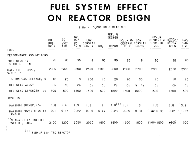


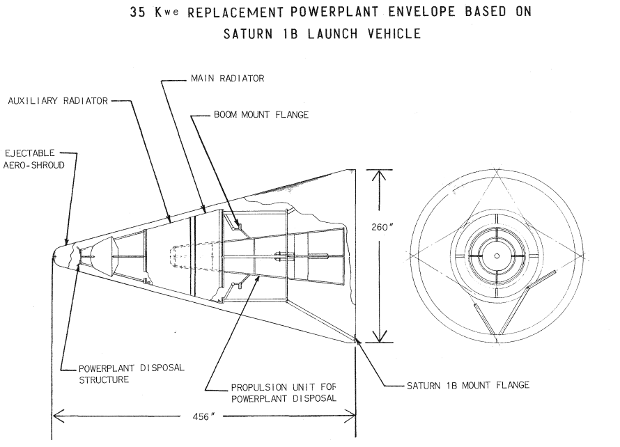


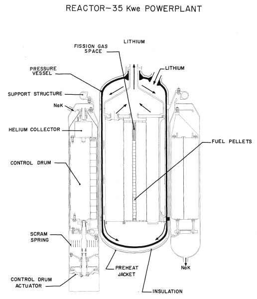


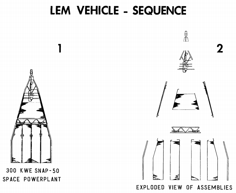
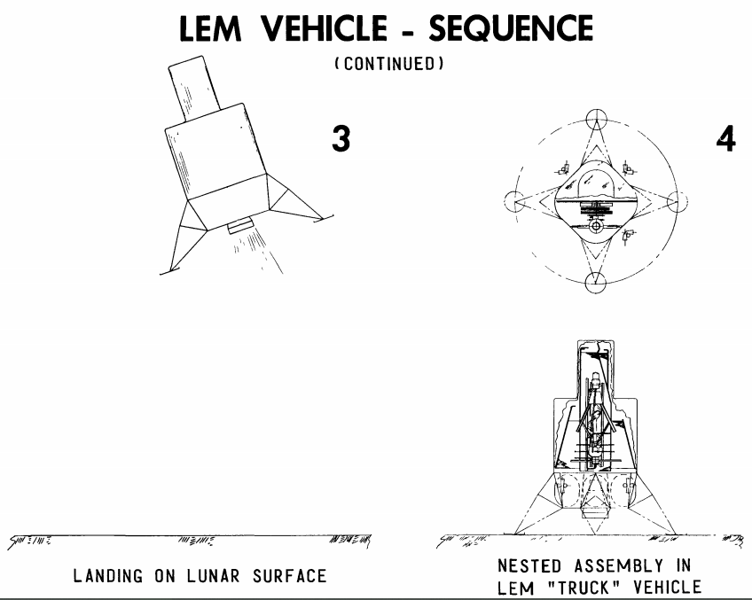
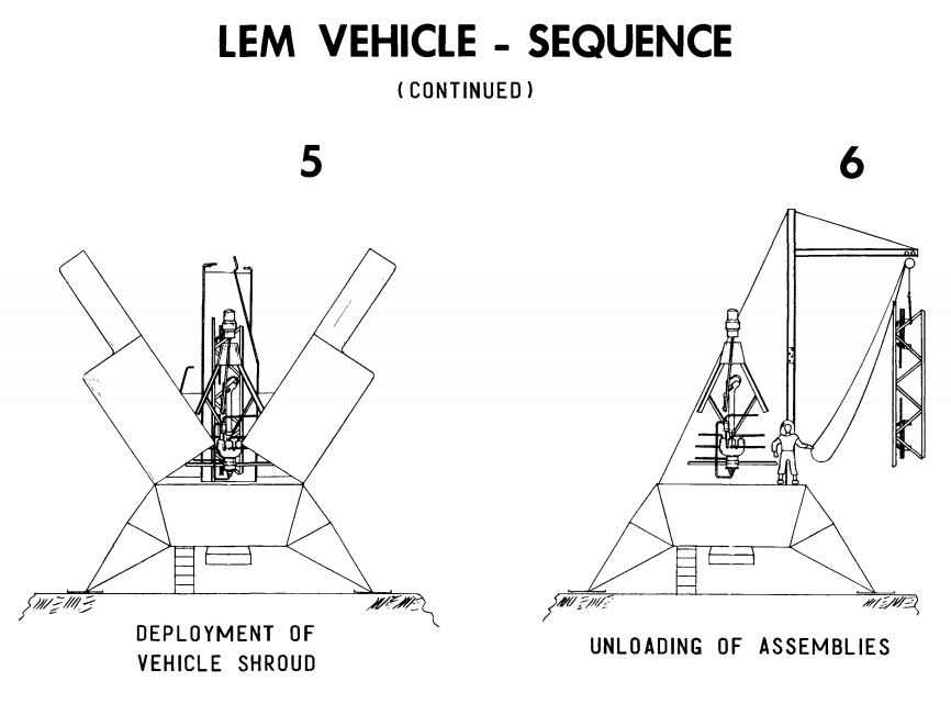
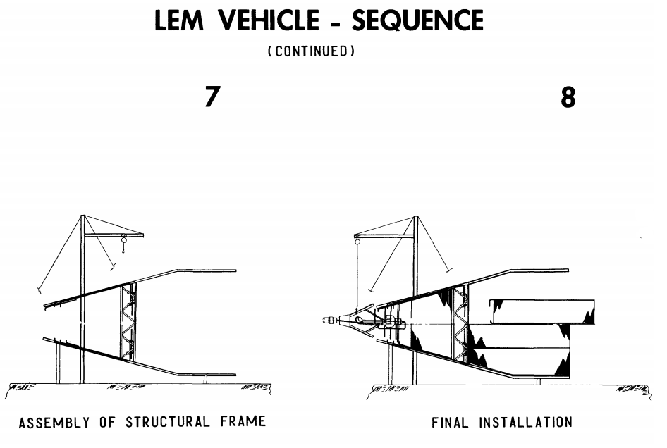


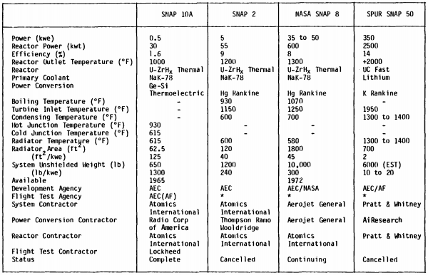


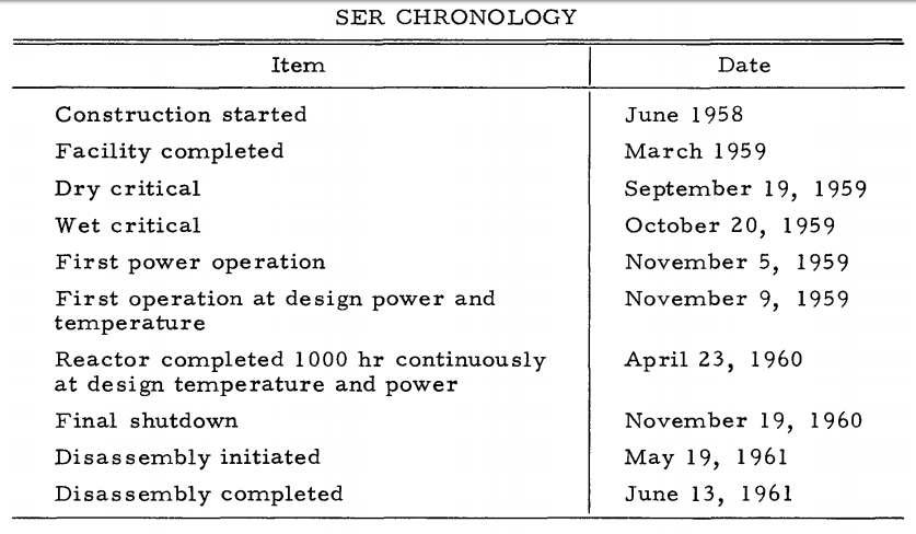


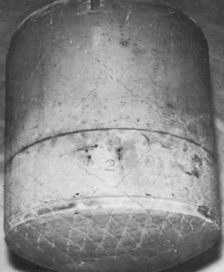
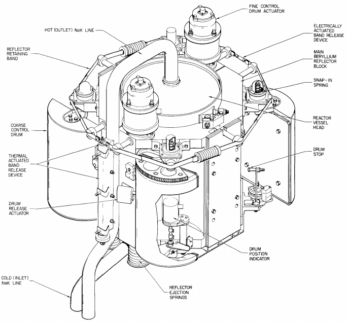
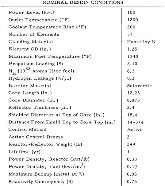
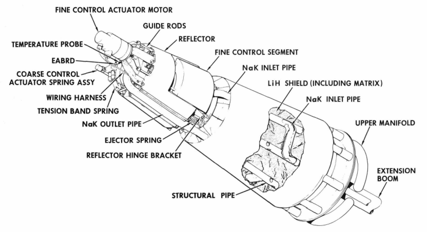
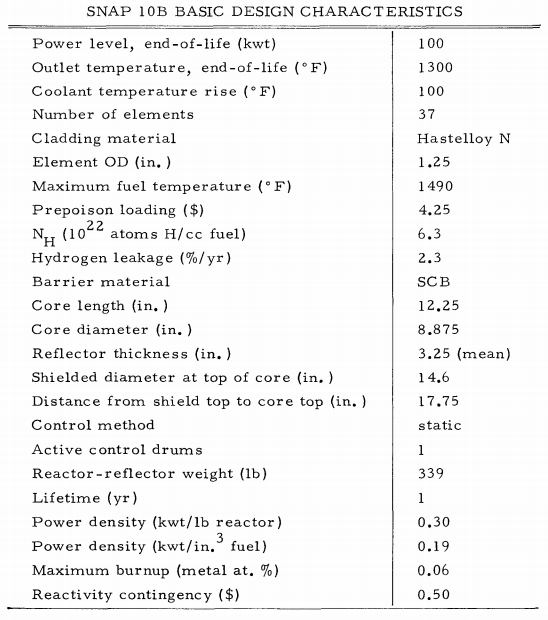


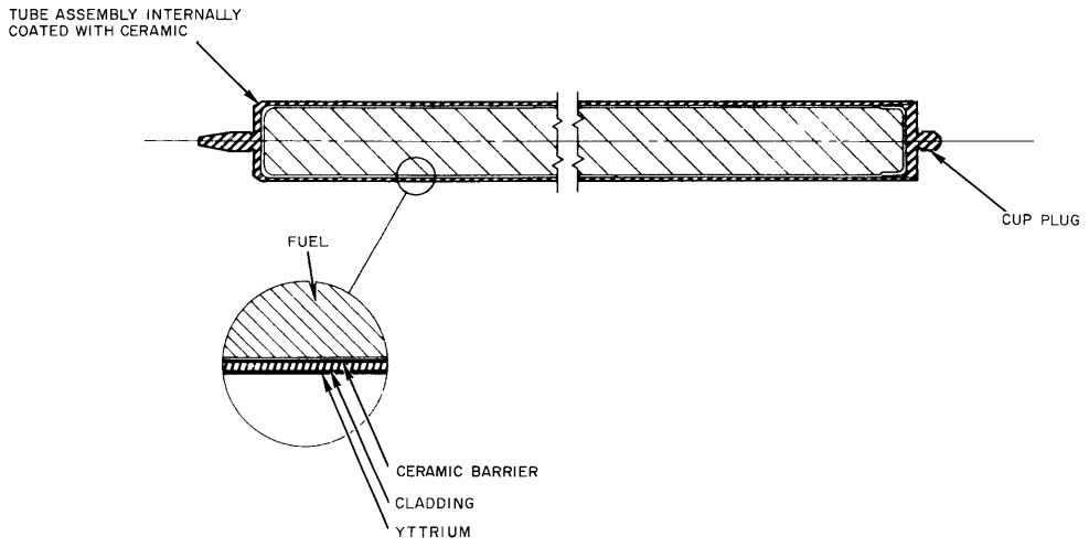
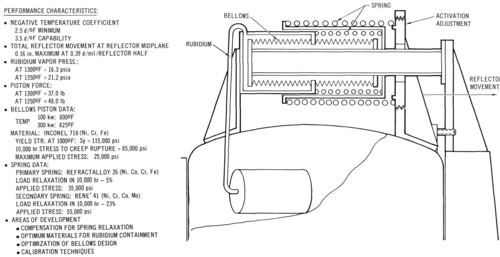
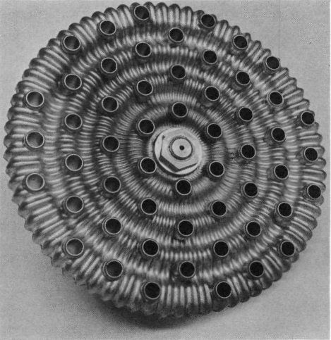 The second option would change the distance between the fuel elements themselves, using base plate with concentric accordion folds for each ring of fuel elements called the “convoluted baseplate.” As the NaK heated beyond optimized design temperature, the base plates would expand radially, separating the fuel elements and reducing the reactivity in the core. This involved a different set of materials tradeoffs, with just getting the device constructed causing major headaches. The design used both 316 stainless steel and Hastelloy C in its construction, and was cold annealed. The alternative, hot annealing, resulted in random cracks, and while explosive manufacture was explored it wasn’t practical to map the shockwave propagation through such a complex structure to ensure reliable construction at the time.
 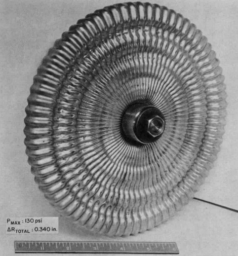 While this is certainly a