Hello, and welcome to Beyond NERVA! Today, we’re continuing to look at the pebble bed nuclear thermal rocket (check out the most recent blog post on the origins of the PBR nuclear thermal rocket here)!
Sorry it took so long to get this out… between the huge amount of time it took just to find the minimal references I was able to get my hands on, the ongoing COVID pandemic, and several IRL challenges, this took me far longer than I wanted – but now it’s here!
Today is special because it is covering one of the cult classics of astronuclear engineering, Project Timber Wind, part of the Strategic Defense Initiative (better known colloquially as “Star Wars”). This was the first time since Project Rover that the US put significant resources into developing a nuclear thermal rocket (NTR). For a number of reasons, Timber Wind has a legendary status among people familiar with NTRs, but isn’t well reported on, and a lot of confusion has built up around the project. It’s also interesting in that it was an incredibly (and according to the US Office of the Inspector General, overly) classified program, which means that there’s still a lot we don’t know about this program 30 years later. However, as one of the most requested topics I hear about, I’m looking forward to sharing what I’ve discovered with you… and honestly I’m kinda blown away with this concept.
Timber Wind was an effort to build a second stage for a booster rocket, to replace the second (and sometimes third) stage of anything from an MX ballistic missile to an Atlas or Delta booster. This could be used for a couple of different purposes: it could be used similarly to an advanced upper stage, increasing the payload capacity of the rocket and the range of orbits that the payload could be placed in; alternatively it could be used to accelerate a kinetic kill vehicle (basically a self-guided orbital bullet) to intercept an incoming enemy intercontinental ballistic missile before it deploys its warheads. Both options were explored, with much of the initial funding coming from the second concept, before the kill vehicle concept was dropped and the slightly more traditional upper stage took precedence.
Initially, I planned on covering both Timber Wind and the Space Nuclear Thermal Propulsion program (which it morphed into) in a single post, but the mission requirements, and even architectures, were too different to incorporate into a single blog post. So, this will end up being a two-parter, with this post focusing on the three early mission proposals for the Department of Defense (DOD) and Strategic Defense Initiative Organization (SDIO): a second stage of an ICBM to launch an anti-booster kinetic kill vehicle, an orbital transfer vehicle (basically a fancy, restartable second stage for a booster), and a multi-megawatt orbital nuclear power plant. The next post will cover when the program became more open, testing became more prevalent, and grander plans were laid out – and some key restrictions on operating parameters eliminated the first and third missions on this list.
Ah, Nomenclature, Let’s Deal with That
So, there’s a couple things to get out of the way before we begin.
The first is the name. If you do a Google/Yandex/etc search for “Timber Wind,” you aren’t going to find much compared to “Timberwind,” but from what I’ve seen in official reporting it should be the other way around. The official name of this program is Project Timber Wind (two words), which according to the information I’ve been able to find is not unusual. The anecdotal evidence I have (and if you know more, please feel free to leave a comment below!) is that for programs classified Top Secret: Special Access (as this was) had a name assigned based on picking two random words via computer, whereas other Top Secret (or Q, or equivalent) programs didn’t necessarily follow this protocol.
However, when I look for information about this program, I constantly see “Timberwind.” not the original “Timber Wind.” I don’t know when this shift happened – it didn’t ever happen with rare exceptions in official documentation, even in the post-cancellation reporting, but somehow public reporting always uses the single word variation. I kinda attribute it to reading typewritten reports when the reader is used to digitally written documents as personal head-canon, but that’s all that explanation is – my guess which makes sense to me.
So there’s a disconnect between what most easily accessible sources use (single word), and the official reporting (two words). I’m going to use the original, because the only reason I’ve gotten as far as I have by being weird about minor details in esoteric reports, so I’m not planning on stopping now (I will tag the single word in the blog, just so people can find this, but that’s as far as I’m going)!
The second is in nuclear reactor geometry definitions.
Having discrete, generally small fuel elements generally falls into two categories: particle beds and pebble beds. Particles are small, pebbles are big, and where the line falls seems to be fuzzy. In modern contexts, the line seems to fall around the 1 cm diameter mark, although finding a formal definition has so far eluded me. However, pebble beds are also a more colloquial term than particle beds in use: a particle bed is a type of pebble bed in common use, but not vice versa.
In this context, both the RBR and Timber Wind are both particle bed reactors, and I’ll call them such, but if a source calls the reactor a pebble bed (which many do), I may end up slipping up and using the term.
OK, nomenclature lesson done. Back to the reactor!
Project Timber Wind: Back to the Future
For those in the know, Timber Wind is legendary. This was the first time after Project Rover that the US put its economic and industrial might behind an NTR program. While there had been programs in nuclear electric propulsion (poorly funded, admittedly, and mostly carried through creative accounting in NASA and the DOE), nuclear thermal propulsion had taken a back seat since 1972, when Project Rover’s continued funding was canceled, along with plans for a crewed Mars mission, a crewed base on the Moon, and a whole lot of other dreams that the Apollo generation grew up on.
There was another difference, as well. Timber Wind wasn’t a NASA program. Despite all the conspiracy theories, the assumptions based on the number of astronauts with military service records, and the number of classified government payloads that NASA has handled, it remains a civilian organization, with the goal of peacefully exploring the solar system in an open and transparent manner. The Department of Defense, on the other hand, is a much more secretive organization, and as such many of the design details of this reactor were more highly classified than is typical in astronuclear engineering as they deal with military systems. However, in recent years, many details have become available on this system, which we’ll cover in brief today – and I will be linking not only my direct sources but all the other information I’ve found below.
Also unlike NTR designs since the earliest days of Rover, Timber Wind was meant to act as a rocket stage during booster flight. Most NTR designs are in-space only: the reactor is launched into a stable, “nuclear-safe” (i.e. a long-term stable orbit with minimal collision risk with other satellites and debris) orbit, then after being mated to the spacecraft is brought to criticality and used for in-space orbital transfers, interplanetary trajectories, and the like. (Interesting aside, this program’s successor seems to be the first time that now-common term was used in American literature on the subject.)
Timber Wind was meant to support the Strategic Defense Initiative (SDI), popularly known as Star Wars. Started in 1983, this extensive program was meant to provide a ballistic missile shield, among other things, for the US, and was given a high priority and funding level for a number of programs. One of these programs, the Boost Phase Intercept vehicle, meant to destroy an intercontinental ballistic missile during the boost phase of the vehicle using a kinetic impactor which would be launched either from the ground or be pre-deployed in space. A kinetic kill vehicle is basically a set of reaction control thrusters designed to guide a small autonomous spacecraft into its target at high velocity and destroy it. They are typically small, very nimble, and limited only by the sensors and autonomous guidance software available for them.
In order to do this, the NTR would need to function as the second stage of a rocket, meaning that while the engine would be fired only after it had entered the lower reaches of space or the upper reaches of the atmosphere (minimizing the radiation risk from the launch), it would still very much be in a sub-orbital flight path at the time, and would have much higher thrust-to-weight ratio requirements as a result.
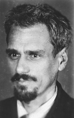
The engine that was selected was based on a design by James Powell at Brookhaven National Laboratory (BNL) in the late 1970s. He presented the design to Grumman in 1982, and from there it came to the attention of the Strategic Defense Initiative Organization (SDIO), the organization responsible for all SDI activities.

SDIO proceeded to break the program up into three phases:
- Phase I (November 1987 to September 1989): verify that the pebblebed reactor concept would meet the requirements of the upper stage of the Boost Phase Intercept vehicle, including the Preliminary Design Review of both the stage and the whole vehicle (an MX first stage, with the PBR second stage /exceeding Earth escape velocity after being ignited outside the atmosphere)
- Phase II (September 1989-October 1991 under SDIO, October 1991-January 1994 when it was canceled under the US Air Force, scheduled completion 1999): Perform all tests to support the ground test of a full PBR NTR system in preparation for a flight test, including fuel testing, final design of the reactor, design and construction of testing facilities, etc. Phase II would be completed with the successful ground hot fire test of the PBR NTR, however the program was canceled before the ground test could be conducted.
- Once the program was transferred to the US Air Force (USAF), the mission envelope expanded from an impactor’s upper stage to a more flexible, on-orbit multi-mission purpose, requiring a design optimization redesign. This is also when NASA became involved in the program.
- Another change was that the program name shifted from Timber Wind to the Space Nuclear Thermal Propulsion program (SNTP), reflecting both the change in management as well as the change in the mission design requirements.
- Once the program was transferred to the US Air Force (USAF), the mission envelope expanded from an impactor’s upper stage to a more flexible, on-orbit multi-mission purpose, requiring a design optimization redesign. This is also when NASA became involved in the program.
- Phase III (never conducted, planned for 2000): Flight test of the SNTP upper stage using an Atlas II launch vehicle to place the NTR into a nuclear-safe orbit. Once on orbit, a number of on-orbit tests would be conducted on the engine, but those were not specified to any degree due to the relatively early cancellation of the program.
While the program offered promise, many factors combined to ensure the program would not be completed. First, the hot fire testing facilities required (two were proposed, one at San Tan and one at the National Nuclear Security Site) would be incredibly expensive to construct, second the Space Exploration Initiative was heavily criticized for reasons of cost (a common problem with early 90’s programs), and third the Clinton administration cut many nuclear research programs in all US federal departments in a very short period of time (the Integral Fast Reactor at Argonne National Laboratory was another program to be cut at about the same time).
The program would be transferred into a combined USAF and NASA program in 1991, and end in 1994 under those auspices, with many successful hurdles overcome, and it remains an attractive design, one which has become a benchmark for pebble bed nuclear thermal rockets, and a favorite of the astronuclear community to speculate what would be possible with this incredible engine.
To understand why it was so attractive, we need to go back to the beginning, in the late 1970s at Brookhaven National Laboratory in the aftermath of the Rotating Fluidized Bed Reactor (RBR, covered in our last post here).
The Beginning of Timber Wind
When we last left particle bed NTRs, the Rotating Fluidized Bed Reactor program had made a lot of progress on many of the fundamental challenges with the concept of a particle bed reactor, but still faced many challenges. However, the team, including Dr. John Powell, were still very enthusiastic about the promise it offered – and conscious of the limitations of the system.
Dr. Powell continued to search for funding for a particle bed reactor (PBR) NTR program, and interest in NTR was growing again in both industry and government circles, but there were no major programs and funding was scarce. In 1982, eight years after the conclusion of the RBR, he had a meeting with executives in the Grumman Corporation, where he made a pitch for the PBR NTR concept. They were interested in the promise of higher specific impulse and greater thrust to weight ratios compared to what had become the legacy NERVA architecture, but there wasn’t really a currently funded niche for the project. However, they remained interested enough to start building a team of contractors willing to work on the concept, in case the US government revived its NTR program. The companies included other major aerospace companies (such as Garrett Corp and Aerojet) and nuclear contractors (such as Babcock and Wilcox), as well as subcontractors for many components.
At the same time, they tried to sell the concept of astronuclear PBR designs to potentially interested organizations: a 1985 briefing to the Air Force Space Division on the possibility of using the PBR as a boost phase interceptor was an early, but major, presentation that would end up being a major part of the initial Timber Wind architecture, and the next year an Air Force Astronautics Laboratory issues a design study contract for a PBR-based Orbital Transfer Vehicle (OTV, a kind of advanced upper stage for an already-existing booster). While neither of these contracts was big enough to do a complete development program, they WERE enough money to continue to advance the design of the PBR, which by now was showing two distinct parts: the boost phase interceptor, and the OTV. There was also a brief flirtation with using the PBR architecture from Timber Wind as a nuclear electric power source, which we’ll examine as well, but this was never particularly well focused on or funded, so remains a footnote in the program.
Reactor Geometry

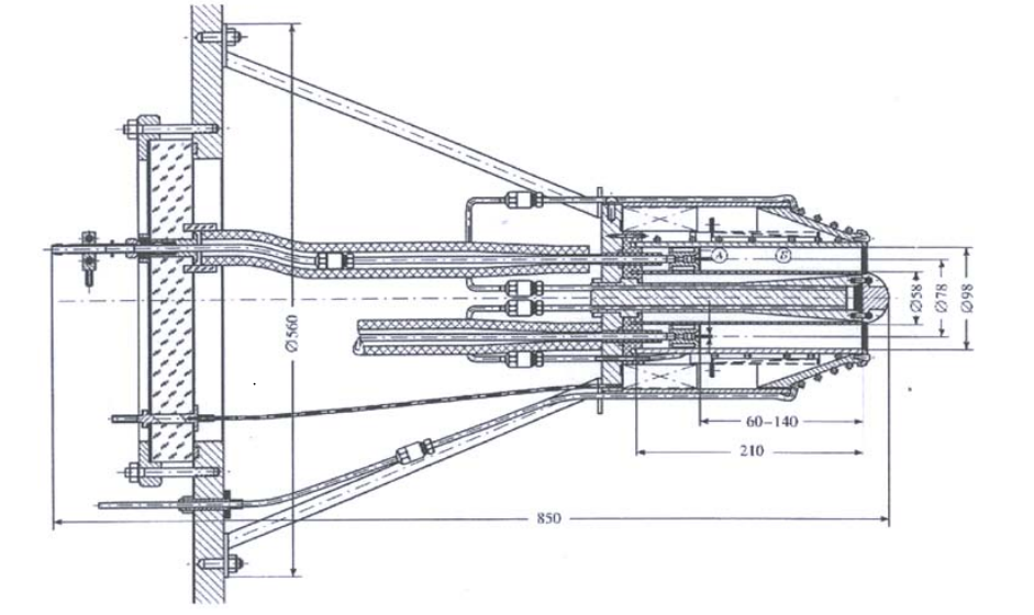
Timber Wind Nuclear Orbital Transfer Vehicle Elevation, Powell et al 1987 
Timber Wind Nuclear Orbital Transfer Vehicle cross section, Horn et al 1986

Timber Wind was a static particle bed reactor, in the general form of a cylinder 50 cm long by 50 cm in diameter, using 19 fuel elements to heat the propellant in a folded flow path. Each fuel element was roughly cylindrical with a 6.4 cm diameter, consisting of a cold frit (a perforated cylinder) made of stainless steel and a hot frit made out of zirconium carbide (ZrC, although rhenium – Rh – clad would also meet thermal and reactivity requirements) coated carbon-carbon composite, which held a total of 125 kg (15 liters) of 500 micron diameter spheres of uranium/zirconium carbide fueled fuel particles which were clad in two layers of different carbon compositions followed by ZrC cladding. These would be held in place through mechanical means, rather than centrifugal force like in the RBR, reducing the mass of the system at the (quite significant materially) cost of developing a hot frit to mechanically contain the fuel. This is something we’ll cover more in depth in the next post.
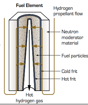
The propellant would then pass into a central, truncated cone central void, becoming wider from the spacecraft to the nozzle end. This is called orificing. An interesting challenge with nuclear reactors is the fact that the distribution of energy generation changes based on location within the reactor, called radial/axial power peaking (something that occurs in individual fuel elements both in isolation and in terms of their location in a core as well, part of why refueling a nuclear reactor is an incredibly complex process), and in this case it was dealt with in a number of ways, but one of the primary ones was individually changing the orificing of each fuel element to accommodate the power generation and propellant flow rate of each fuel element.
Along these lines, another advantage of this type of core is the ability to precisely control the amount of fissile fuel in each fuel element along the length of the reactor, and along the radius of the fuel element. Since the fuel particles are so small, and the manufacturing of each would be a small-batch process (even fueling a hundred of these things would only take 1500 liters of volume, with the fissile component of that volume being a small percentage of that), a variety of fuel loading options were inherently available, and adjustments to power distribution were reasonably easy to achieve from reactor to reactor. This homogenizes power distribution in some reactors, and increases local power in other, more specialized reactors (like some types of NTRs), but here an even power distribution along the length of the fuel element is desired. This power leveling is done in virtually every fuel element in every reactor, but is a difficult and complex process with large fuel elements due to the need to change how much U is in each portion of the fuel elements. With a particle bed reactor, on the other hand, the U content doesn’t need to vary inside each individual fuel paritcles, and both fueled and unfueled particles can be added in specific regions of the fuel element to achieve the desired power balance within the element. There was actually a region of unfueled particles on the last cm of the particle bed in each fuel element to maximize the efficiency of power distribution into the propellant, and the level of enrichment for the 235U fuel was varied from 70% to 93.5% throughout the fueled portions. This resulted in an incredibly flat power profile, with a ratio of only 1.01:1 from the peak power density to the average power density.
Since the propellant would pass from the outside of each fuel element to the inside, cooling the reactor was far easier, and lower-mass (or higher efficiency) options for things such as moderator were an option. This is a benefit of what’s called a folded-flow propellant path, something that we’ve discussed before in some depth in our post on Dumbo, the first folded flow NTR concept [insert link]. In short, instead of heating the propellant as it passes down the length of the reactor such as in Rover, a folded flow injects the cold propellant laterally into the fuel element, heating it in a very short distance, and ejecting it through a central void in the fuel element. This has the advantage of keeping the vast majority of the reactor very cool, eliminating many of the thermal structural problems that Rover experienced, at the cost of a more complex gasdynamic behavior system. This also allowed for lighter-weight materials to be used in the construction, such as aluminum structural members and pressure vessel, to further reduce the mass of the reactor.
Interestingly, many of these lower-mass options, such as Li7H moderator, were never explored, since the mass of the reactor came in at only about 0.6 tons, a very small number compared to the 10 ton payload, so it just wasn’t seen as a big enough issue to continue working on at that point.
Finally, because of the low (~1 hr) operating time of the reactor, radiation problems were minimized. With a reactor only shielded by propellant, tankage, and the structures of the NTR itself, it’s estimated that the NOTV would subject its payload to a total of 100 Gy of gamma radiation and a neutron fluence of less than 10^14 n/cm^2. Obviously, reducing this for a crewed mission would be necessary, but depending on the robotic mission payload, additional shielding may not be necessary. The residual radiation would also be minimal due to the short burn time, although if the reactor was reused this would grow over time.
In 1987, the estimated cost per unit (not including development and testing was about $4 million, a surprisingly low number, due to the ease of construction, low thermal stresses requiring fewer exotic materials and solutions, and low uranium load requirements.
This design would continue to evolve throughout Timber Wind and into SNTP as mission requirements changed (this description is based on a 1987 paper linked below), and we’ll look at the final design in the next post.
For now, let’s move on to how this reactor would be used.
Nuclear Thermal Kinetic Kill Vehicle
The true break for the project came in the same year: 1987. This is when the SDIO picked the Brookhaven (and now Grumman) concept as their best option for a nuclear-enhanced booster for their proposed ground deployed boost phase interceptor.
I don’t do nuclear weapons coverage, in fact that’s a large part of why I’ve never covered systems like Pluto here, but it is something that I’ve gained some knowledge of through osmosis through interactions with many intelligent and well-educated people on social media and in real life… but this time I’m going to make a slight exception for strategic ballistic missile shield technology, because an NTR powered booster is… extremely rare. I can think of four American proposals that continued to be pursued after the 1950s, one early (apocryphal) Soviet design in the early 1950s, one modern Chinese concept, and that’s it! I get asked about it relatively frequently, and my answer is basically always the same: unless something significant changes, it’s not a great idea, but in certain contexts it may work. I leave it up to the reader to decide if this is a good context. (The list I can think of is the Reactor In-Flight Test, or RIFT, which was the first major casualty of Rover/NERVA cutbacks; Timber Wind; and for private proposals the Liberty Ship nuclear lightbulb booster and the Nuclear Thermal Turbo Rocket single stage to orbit concept).
So, the idea behind boost stage interception is that it targets an intercontinental ballistic missile and destroys the vehicle while it’s still gaining velocity – the earlier the interception that can destroy the vehicle, the better. There were many ideas on how to do this, including high powered lasers, but the simplest idea (in theory, not in execution) was the kinetic impactor: basically a self-guided projectile would hit the very thin fuel or oxidizer tanks of the ICBM, and… boom, no more ICBM. This was especially attractive since, by this time, missiles could carry over a dozen warheads, and this would take care of all of them at once, rather than a terminal phase interceptor, which would have to deal with each warhead individually.
The general idea behind Timber Wind was that a three-stage weapon would be used to deliver a boost-phase kinetic kill vehicle. The original first stage was based on the LGM-118 Peacekeeper (“MX,” or Missile – Experimental) first stage, which had just deployed two years earlier. This solid fueled ICBM first stage normally used a 500,000 lbf (2.2 MN) SR118 solid rocket motor, although it’s not clear if this engine was modified in any way for Timber Wind. The second stage would be the PBNTR Timber Wind stage, which would achieve Earth escape velocity to prevent reactor re-entry, and the third stage was the kinetic kill vehicle (which I have not been able to find information about).
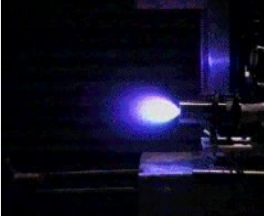
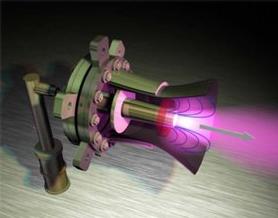
Here’s a recent Lockheed Martin KKV undergoing testing, so you can get an idea of what this “bullet” looks and behaves like: https://www.youtube.com/watch?v=KBMU6l6GsdM
Needless to say, this would be a very interesting launch profile, and one that I have not seen detailed anywhere online. It would also be incredibly challenging to
- detect the launch of an ICBM;
- counter-launch even as rapid-fire-capable a missile as a Peacekeeper;
- provide sufficient guidance to the missile in real-time to guide the entire stack to interception;
- go through three staging events (two of which were greater than Earth escape velocity!);
- guide the kinetic kill vehicle to the target with sufficient maneuvering capability to intercept the target;
- and finally have a reasonably high chance of mission success, which required both the reactor to go flying off into a heliocentric orbit and have the kinetic kill vehicle impact the target booster
all before the second (or third) staging event for the target ICBM (i.e. before warhead deployment).
This presents a number of challenges to the designers: thrust-to-weight ratio is key to a booster stage, something that to this point (and even today) NTRs struggle with – mostly due to shielding requirements for the payload.
There simply isn’t a way to mitigate gamma radiation in particular without high atomic number nuclei to absorb and re-emit these high energy photons enough times that a lighter shielding material can be used to either stop or deflect the great-great-great-great-…-great grand-daughter photons from sensitive payloads, whether crew or electronics. However, electronics are far less sensitive than humans to this sort of irradiation, so right off the bat this program had an advantage over Rover: there weren’t any people on board, so shielding mass could be minimized.
Ed. Note: figuring out shielded T/W ratio in this field is… interesting to say the least. It’s an open question whether reported T/W includes anything but the thrust structure (i.e. no turbopumps and associated hardware, generally called the “power pack” in rocket engineering), much less whether it includes shielding – and the amount of necessary shielding is another complex question which changes with time. Considering the age of many of these studies, and the advances in computational capability to model not only the radiation being emitted from the reactor vessel but the shielding ability of many different materials, every estimate of required shielding must be taken with 2-3 dump trucks of salt!!! Given that shielding is an integral part of the reactor system, this makes pretty much every T/W estimate questionable.
One of the major challenges of the program, apparently, was to ensure that the reactor would not re-enter the atmosphere, meaning that it had to achieve Earth orbit escape velocity, while still able to deploy the third stage kinetic kill vehicle. I’ve been trying to figure out this staging event for a while now, and have come to the conclusion that my orbital mechanics capabilities simply aren’t good enough to assess how difficult this is beyond “exceptionally difficult.”
However, details of this portion of the program were more highly classified than even the already-highly-classified program, and incredibly few details are available about this portion in specific. We do know that by 1991, the beginning of Phase II of Timber Wind, this portion of the program had been de-emphasized, so apparently the program managers also found it either impractical or no longer necessary, focusing instead on the Nuclear Orbital Transfer Vehicle, or NOTV.
PBR-NOTV: Advanced Upper Stage Flexibility

At the same time as Timber Wind was gaining steam, the OTV concept was going through a major evolution into the PBR-NOTV (Particle Bed Reactor – Nuclear Orbital Transfer Vehicle). This was another interesting concept, and one which played around with many concepts that are often discussed in the astronuclear field (some related to pebble bed reactors, some related to NTRs), but are almost never realized.
The goals were… modest…
- ~1000 s isp
- multi-meganewton thrust
- ~50% payload mass fraction from LEO to GEO
- LEO to GEO transfer time measured in hours, burn time measured in minutes
- Customizable propellant usage to change thrust level from same reactor (H2, NH3, and mixtures of the two)

These NOTVs were designed to be the second stage of a booster, similar to the KKV concept we discussed above, but rather than deliver a small kinetic impactor and then leave the cislunar system, these would be designed to place payloads into specific orbits (low Earth orbit, or LEO, mid-Earth orbit, or MEO, and geostationary orbit, GEO, as well as polar and retrograde orbits) using rockets which would normally be far too small to achieve these mission goals. Since the reactor and nozzle were quite small, it was envisioned that a variety of launch vehicles could be used as a first stage, and the tanks for the NTR could be adjusted in size to meet both mission requirements and launch vehicle dimensions. By 1987, there was even discussion of launching it in the Space Shuttle cargo bay, since (until it was taken critical) the level of danger to the crew was negligible due to the lack of oxidizer on board (a major problem facing the Shuttle-launched Centaur with its chemical engine).

There were a variety of missions that the NOTV was designed around, including single-use missions which would go to LEO/MEO/GEO, drop off the payload, and then go into a graveyard orbit for disposal, as well as two way space tug missions. The possibility of on-orbit propellant reloading was also discussed, with propellant being stored in an orbiting depot, for longer term missions. While it wasn’t discussed (since there was no military need) the stage could easily have handled interplanetary missions, but those proposals would come only after NASA got involved.

Multiple Propellants: a Novel Solution to Novel Challenges with Novel Complications
In order to achieve these different orbits, and account for many of the orbital mechanical considerations of launching satellites into particular orbits, a novel scheme for adjusting both thrust and specific impulse was devised: use a more flexible propellant scheme than just cryogenic H2. In this case, the proposal was to use NH3, H2, or a combination of the two. It was observed that the most efficient method of using the two-propellant mode was to use the NH3 first, followed by the H2, since thrust is more important earlier in the booster flight model. One paper observed that in a Hohman transfer orbit, the first part of the perigee burn would use ammonia, followed by the hydrogen to finish the burn (and I presume to circularize the orbit at the end).


When pure ammonia was used, the specific impulse of the stage was reduced to only 500 s isp (compared to the 200-300 s for most second stages), but the thrust would double from 10,000 lbs to 20,000 lbs. By the time the gas had passed into the nozzle, it would have effectively completely dissociated into 3H2 + N2.
One of the main advantages of the composite system is that it significantly reduced the propellant volume needed for the NTR, a key consideration for some of the boosters that were being investigated. In both the Shuttle and Titan rockets, center of gravity and NTR+payload length were a concern, as was volume.
Sadly, there was also a significant (5,000 lb) decrease in payload advantage over the Centaur using NH3 instead of pure H2, but the overall thrust budget could be maintained.
There’s quite a few complications to consider in this design: first, hydrogen behaves very differently than ammonia in a turbopump, not only due to density but also due to compressability: while NH3 is minimally compressible, meaning that it can be considered to have a constant volume for a given pressure and temperature while being accelerated by the turbopump, hydrogen is INCREDIBLY compressible, leading to a lot of the difficulties in designing the power pack (turbopumps, turbines, and supporting hardware of a rocket) for a hydrogen system. It is likely (although not explicitly stated) that at least two turbopumps and two turbines would be needed for this scheme, meaning increased system mass.
Next is chemical sensitivities and complications from the different propellants: while NH3 is far less reactive than H2 at the temperatures an NTR operates at, it nevertheless has its own set of behaviors which have to be accounted for in both chemical reactions and thermal behavior. Ammonia is far more opaque to radiation than hydrogen, for instance, so it’ll pick up a lot more energy from the reactor. This in turn will change the thermal reactivity behavior, which might require the reactor to run at a higher power level with NH3 than it would with H2 to maintain reactor equilibrium.
This leads us neatly into the next behavioral difference: NH3 will expand less than H2 when heated to the same temperature, but at these higher temps the molecule itself may (or will) start to dissociate, as the thermal energy in the molecule exceeds the bonding strength between the covalent bonds in the propellant. This means you’ve now got monatomic hydrogen and various partially-deconstructed nitrogen complexes with different masses and densities to deal with – although this dissociation does decrease propellant mass, increasing specific impulse, and none of the constituent atoms are solids so plating material into your reactor won’t be a concern. These gasdynamic differences have many knock-on effects though, including engine orificing.
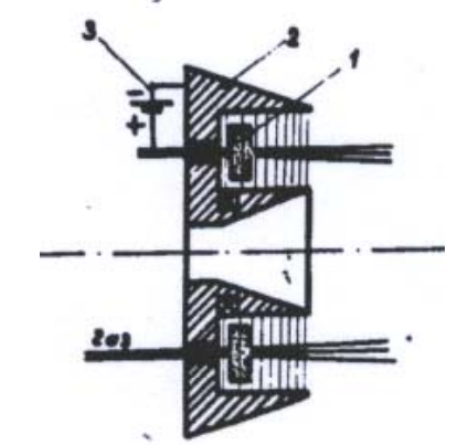
See how the top end of the fuel element’s central void is so much narrower than the bottom? One of the reasons for this is that the propellant is hotter – and therefore less dense – at the bottom (it’s also because as you travel down the fuel element more and more propellant is being added). This is something you see in prismatic fuel elements as well, but it’s not something I’ve seen depicted well anywhere so I don’t have as handy a diagram to use.
This taper is called “orificing,” and is used to balance the propellant pressure within an NTR. It depends on the thermal capacity of the propellant, how much it expands, and how much pressure is desired at that particular portion of the reactor – and the result of these calculations is different for NH3 and H2! So some compromises would have to be reached in this cases as well.
Finally, the tankage for the propellant is another complex question. The H2 has to be stored at such a lower temperature compared to the NH3 that a common bulkhead between the tanks simply wouldn’t be possible – the hydrogen would freeze the ammonia. This could lead to a failure mode similar to what happened to SpaceX’s Falcon 9 in September 2016, when the helium tanks became super-chilled and then ruptured on the pad leading to the loss of the vehicle. Of course, the details would be different, but the danger is the same. This leads to the necessity for a complex tankage system in addition to the problems with the power pack that we discussed earlier.


All of this leads to a heavier and heavier system, with more compromises overall, and with a variety of reactor architectures being discussed it was time to consolidate the program.
Multi-Megawatt Power: Electricity Generation
While all these studies were going on, other portions of SDIO were also undergoing studies in astronuclear power systems. The primary electric power system was the SP-100, a multi-hundred kilowatt power supply using technology that had evolved out of the SNAP reactor program in the 60s and 70s. While this program was far along in its development, it was over budget, delayed, and simply couldn’t provide enough power for some of the more ambitious projects within SDIO. Because of this, SDIO (briefly) investigated higher power reactors for their more ambitious – and power-hungry – on-orbit systems.
Power generation was something that was often discussed for pebble bed reactors – the same reasons that make the concept phenomenal for nuclear thermal rockets makes a very attractive high temperature gas cooled reactors (HTGR): the high thermal transfer rates reduce the size of the needed reactor, while the pebble bed allows for very high gas flow rates (necessary due to the low thermal capacity of the coolant in an HTGR). To do this, the gas doesn’t go through a nozzle, but instead through a gas turbine – known as the Brayton cycle. This has huge efficiency advantages over thermoelectric generators, the design being used in SP-100, meaning that the same size reactor can generate much more electricity – but this would definitely not be the same size reactor!
The team behind Timber Wind (including the BNL, SNL and B&W teams) started discussing both electric generation and bimodal nuclear thermal and nuclear electric reactor geometry as early as 1986, before SDIO picked up the program. Let’s take a look at the two proposals by the team, starting with the bimodal proposal.
Particle Bed BNTR: A Hybrid of a Hybrid

The bimodal NTR (BNTR) system never gained any traction, despite it being a potentially valuable addition to the NOTV concept. It is likely that the combination of the increased complexity and mass of the BNTR compared to the design that was finally decided on for Timber Wind, but it was interesting to the team, and they figured someone may be interested as well. This design used the same coolant channels for both the propellant and coolant, which in this case was He. This allowed for similar thermal expansion characteristics and ass flow in the coolant compared to the propellant, while minimizing both corrosion and gas escape challenges.

A total of 37 fuel elements, similar to those used on Timber Wind, were placed in a triangular configuration, with zirconium hydride moderator surrounding them, with twelve control rods for reactivity control. Unusually for many power generation systems, this concept used a conbination of low power, closed loop coolant (using He) and a high power open loop system using H2, which would then be vented out into space through a nozzle (this second option was limited to about 30 mins of high power operation before exhausting H2 reserves). A pair of He Brayton turbines and a radiator was integrated into the BNTR structure. The low power system was designed to operate for “years at a time,” producing 555 kWe of power, while the high power system was rated to 100 Mwe in either rapid ramp or burst mode.

However, due to the very preliminary nature of this design very few things are completely fleshed out in the only report on the concept that I’ve been able to find. The images, such as they are, are also disappointingly poor in quality, but provide at least a vague idea of the geometry and layout of the reactor:

Multi-Megawatt Steady State and Burst Reactor Proposal
By 1989, two years into Timber Wind, SDIO wanted a powerful nuclear reactor to provide two different power configurations: a steady state, 10 Mwe reactor with a 1 year full power lifetime, which was also able to provide bursts of up to 500 MW for long enough to power neutral particle beams and free electron lasers. A variety of proposals were made, including an adaptation of Timber Wind’s reactor core, an adaptation of a NERVA A6 type core (the same family of NERVA reactors used in XE-Prime), a Project Pluto-based core, a hybrid NERVA/Pluto core, a larger, pellet fueled reactor, and two rarer types of fuel: a wire core reactor and a foam fueled reactor. This is in addition to both thermionic and metal Rankine power systems.
The designs for a PBR-based reactor, though, were very different than the Timber Wind reactor. While using the same TRISO-type fuel, they bear little resemblance to the initial reactor proposal. Both the open and closed cycle concepts were explored.

However, this concept, while considered promising, was passed over in preference for more mature fuel forms (under different reactor configurations, namely a NERVA-derived gas reactor.


Finding information about this system is… a major challenge, and one that I’m continuing to work on, but considering this is the best summary I’ve been able to find based on over a week’s searching for source material which as far as I can tel is still classified or has never been digitally documented, as unsatisfying a summary as this is I’m going to leave it here for now.
When I come back to nuclear electric concepts. we’ll come back to this study. I’ve got… words… about it, but at the present moment it’s not something I’m comfortable enough to comment on (within my very limited expertise).
Phase I Experiments
The initial portion of Timber Wind, Phase I, wasn’t just a paper study. Due to the lack of experience with PBR reactors, fuel elements, and integrating them into an NTR, a pair of experiments were run to verify that this architecture was actually workable, with more experiments being devised for Phase II.

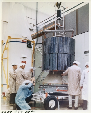
The first of these tests was PIPE (Pulse Irradiation of a Particle Bed Fuel Element), a test of the irradiation behavior of the PBR fuel element which was divided into two testing regimes in 1988 and 1989 at Sandia National Laboratory’s Annular Core Research Reactor using fuel elements manufactured by Babcock and Wilcox. While the ACCR prevented the power density of the fuel elements to achieve what was desired for the full PBR, the data indicated that the optimism about the potential power densities was justified. Exhaust temperatures were close to that needed for an NTR, so the program continued to move forward. Sadly, there were some manufacturing and corrosion issues with the fuel elements in PIPE-II, leading to some carbon contamination in the test loop, but this didn’t impact the ability to gather the necessary data or reduce the promise of the system (just created more work for the team at SNL).
A later test, PIPET (Particle Bed Reactor Integral Performance Tester) began undergoing preliminary design reviews at the same time, which would end up consuming a huge amount of time and money while growing more and more important to the later program (more on that in the next post).
The other major test to occur at this time was CX1, or Critical Experiment 1.

Carried out at Sandia National Laboratory, CX1 was a novel configuration of prototypic fuel elements and a non-prototypical moderator to verify the nuclear worth of fuel elements in a reactor environment and then conduct post-irradiation testing. This sort of testing is vitally important to any new fuel element, since the computer modeling used to estimate reactor designs requires experimental data to confirm the required assumptions used in the calculations.
This novel architecture looked nothing like an NTR, since it was a research test-bed. In fact, because it was a low power system there wasn’t much need for many of the support structures a nuclear reactor generally uses. Instead, it used 19 fuel elements placed within polyethylene moderator plugs, which were surrounded by a tank of water for both neutron reflection and moderation. This was used to analyze a host of different characteristics, from prompt neutron production (since the delayed neutron behavior would be dependent on other materials, this wasn’t a major focus of the testing), as well as initial criticality and excess reactivity produced by the fuel elements in this configuration.
CX-1 was the first of two critical experiments carried out using the same facilities in Sandia, and led to further testing configurations, but we’ll discuss those more in the next post.
Phase II: Moving Forward, Moving Up
With the success of the programmatic, computational and basic experiments in Phase I, it was time for the program to focus on a particular mission type, prepare for ground (and eventual flight) testing, and move forward.

This began Phase II of the program, which would continue from the foundation of Phase I until a flight test was able to be flown. By this point, ground testing would be completed, and the program would be in a roughly similar position to NERVA after the XE-Prime test.
Phase II began in 1990 under the SDIO, and would continue under their auspices until October 1991. The design was narrowed further, focusing on the NOTV concept, which was renamed the Orbital Maneuvering Vehicle.
Many decisions were made at this point which I’ll go into more in the next post, but some of the major decisions were:
- 40,000 lbf (~175 kN) thrust level
- 1000 MWt power level
- Hot bleed cycle power pack configuration
- T/W of 20:1
- Initial isp est of 930 s
While this is a less ambitious reactor, it could be improved as the program matured and certain challenges, especially in materials and reactor dynamics uncertainties, were overcome.
Another critical experiment (CX2) was conducted at Sandia, not only further refining the nuclear properties of the fuel but also demonstrating a unique control system, called a “Peek-A-Boo” scheme. Here, revolving rings made up of aluminum and gadolinium surrounded the central fuel element, and would be rotated to either absorb neutrons or allow them to interact with the other fuel elements. While the test was promising (the worth of the system was $1.81 closed and $5.02 open, both close to calculated values), but this system would not end up being used in the final design.
Changing of the Guard: Timber Wind Falls to Space Nuclear Thermal Propulsion
Even as Timber Wind was being proposed, tensions with the USSR had been falling. By the time it got going in 1987, tensions were at an all-time low, reducing the priority of the SDIO mission. Finally, the Soviet Union fell, eliminating the need for the KKV concept.
At the same time, the program was meeting its goals (for the most part), and showed promise not just for SDIO but for the US Air Force (who were responsible for launching satellites for DOD and intelligence agencies) as well as NASA.
1990 was a major threshold year for the program. After a number of Senate-requested assessments by the Defense Science Board, as well as assessment by NASA, the program was looking like it was finding a new home, one with a less (but still significantly) military-oriented focus, and with a civilian component as well.
The end of Timber Wind would come in 1991. Control of the program would transfer from SDIO to the US Air Force, which would locate the programmatic center of the project at the Phillips Research Laboratory in Albuquerque, NM – a logical choice due to the close proximity of Sandia National Lab where much of the nuclear analysis was taking place, as well as being a major hub of astronuclear research (the TOPAZ International program was being conducted there as well). Additional stakes in the program were given to NASA, which saw the potential of the system for both uncrewed and crewed missions from LEO to the Moon and beyond.
With this, Timber Wind stopped being a thing, and the Space Nuclear Thermal Propulsion program picked up basically exactly where it left off.
The Promise of SNTP
With the demise of Timber Wind, the Space Nuclear Thermal Propulsion program gained steam. Being a wider collaboration between different portions of the US government, both civil and military, gave a lot of advantages, wider funding, and more mission options, but also brought its’ own problems.
In the next post, we’ll look at this program, what its plans, results, and complications were, and what the legacy of this program was.
References and Further Reading
Timber Wind/SNTP General References
Haslett, E. A. “SPACE NUCLEAR THERMAL PROPULSION
PROGRAM FINAL REPORT“
https://apps.dtic.mil/dtic/tr/fulltext/u2/a305996.pdf
Orbital Transfer Vehicle
Powell et al, “NUCLEAR PROPULSION SYSTEMS FOR ORBIT TRANSFER BASED ON THE
PARTICLE BED REACTOR” Brookhaven NL 1987 https://www.osti.gov/servlets/purl/6383303
Araj et al, “ULTRA-HIGH TEMPERATURE DIRECT PROPULSION”” Brookhaven NL 1987 https://www.osti.gov/servlets/purl/6430200
Horn et al, “The Use of Nuclear Power for Bimodal Applications in Space,” Brookhaven NL 1987 https://www.osti.gov/servlets/purl/5555461
Multi-Megawatt Power Plant
Powell et al “HIGH POWER DENSITY REACTORS BASED ON
DIRECT COOLED PARTICLE BEDS” Brookhaven NL 1987 https://inis.iaea.org/collection/NCLCollectionStore/_Public/17/078/17078909.pdf
Marshall, A.C “A Review of Gas-Cooled Reactor
Concepts for SDI Applications” Sandia NL 1987 https://www.osti.gov/servlets/purl/5619371
“Atomic Power in Space: a History, chapter 15” https://inl.gov/wp-content/uploads/2017/08/AtomicPowerInSpaceII-AHistory_2015_chapters6-10.pdf


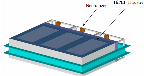


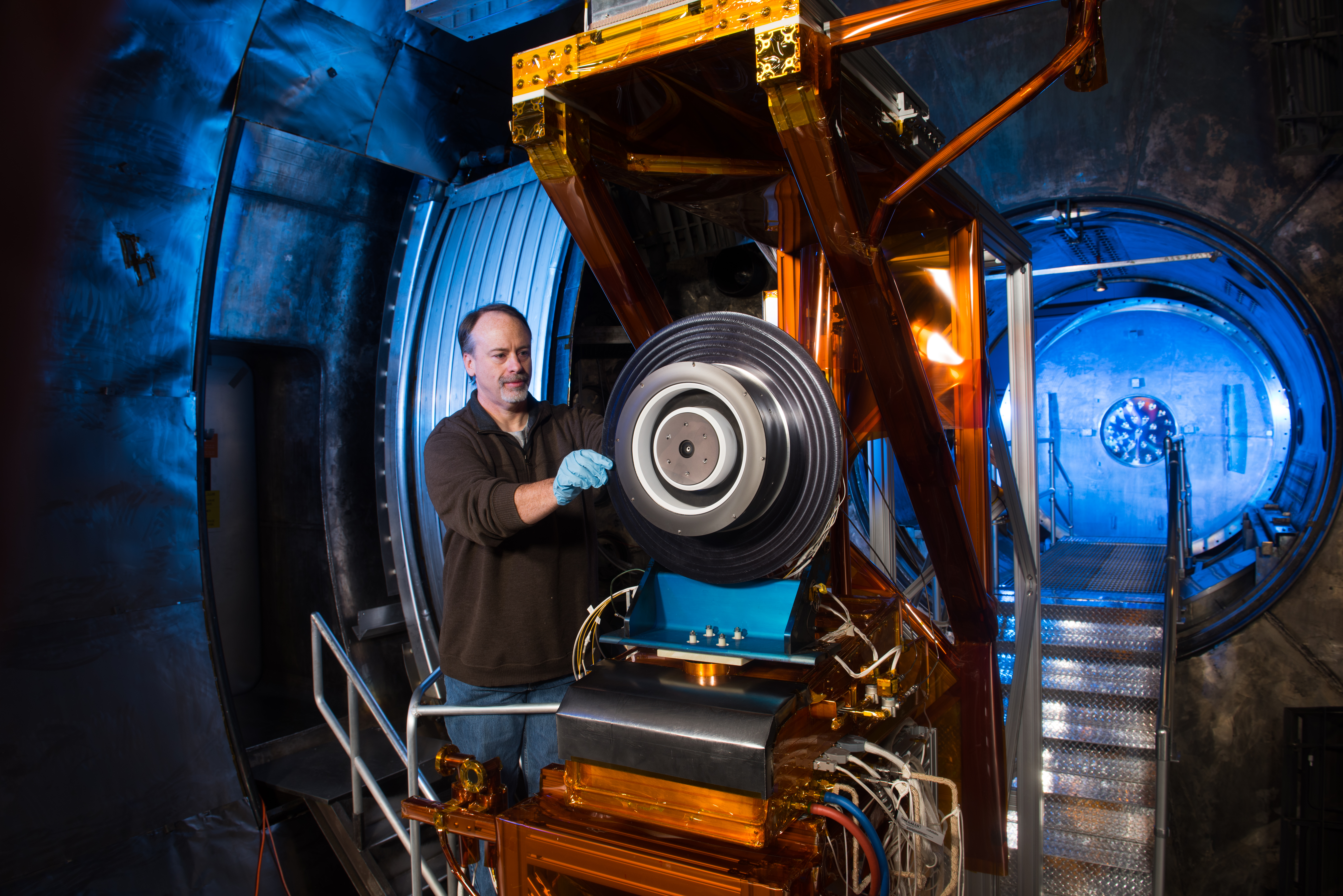
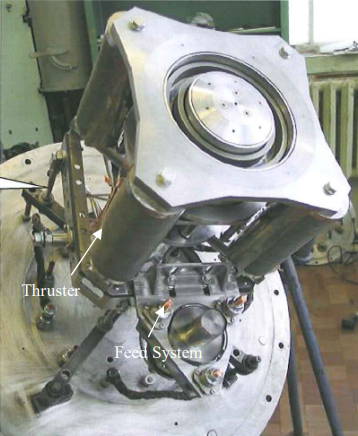
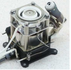
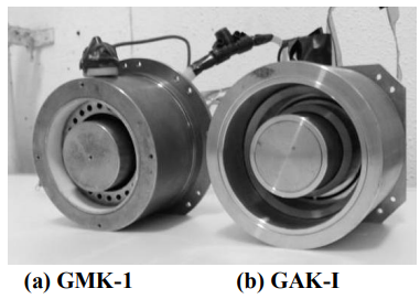
 This thruster is designed to operate as part of a 40 kW system, meaning that three thrusters will be clustered together (complications in clustering Hall thrusters will be covered later as part of the Japanese RIAJIN TAL system). Each thruster has a central hollow cathode, and is optimized for xenon propellant.


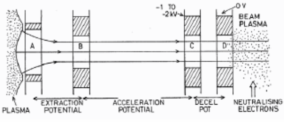
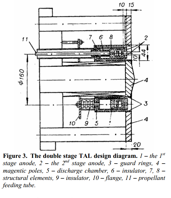 One of the most interesting concepts investigated at TsNIIMash was the dual-stage TAL, which used two anodes. The first anode is very similar to the one used in a typical TAL or SPT, which also serves as an injector for the majority of the propellant and provides the charge to ionize the propellant. As the plasma exits this first anode, it encounters a second anode at the opening of the propellant channel, which accelerates the propellant. An external cathode is used to neutralize the beam. This design demonstrated specific impulses of up to 8000s, among the highest (if not