Hello, and welcome back to Beyond NERVA! My apologies for the delay in this post, electric propulsion is not one of my strong points, so I spent a lot of extra time on research and in discussion with people who are more knowledgeable than I am on this subject. Special thanks to both Roland A. Gabrielli and Mikkel Haaheim for their invaluable help, not only for extensively picking their brains but also for their excellent help in editing (and sometimes rewriting large sections of) this post.
Today, we continue looking at electric propulsion, by starting to look at electrothermal and magnetoplasmadynamic (MPD) propulsion. Because there’s a fair bit of overlap, and because there are a lot of similarities in design, between these two types of thruster, we’ll start here, and then move to electrostatic thrusters in the next post.
As we saw in the last post, there are many ways to produce thrust using electricity, and many different components are shared between the different thruster types. This is most clear, though, when looking at thermal and plasma-dynamic thrusters, as we will see in this post. I’ve also made a compromise on this post’s structure: there are a few different types of thruster that fall in the gray area between thermal and MPD thrusters, but rather than writing about it between the two thruster types, one will be left for last: VASIMR, the Variable Specific Impulse Magnetoplasma Rocket. This thruster has captured the public’s imagination like few types of electric propulsion ever have; and, sadly, this has bred an incredible amount of clickbait. At the end of this post, I hope to lay to rest some of the misconceptions, and look at not only the advantages of this type of thruster, but the limitations as well. This will involve looking a little bit into mission planning and orbital mechanics, an area that we haven’t addressed much in this blog, but I hope to keep it relatively simple.
Electrothermal Propulsion
This is, to put it simply, the use of electric heaters to energize a propellant and to produce thrust by expanding it. In the most primitive and low energy thrusters, this is done with a Laval nozzle as in chemical and other thermal engines. This can be an inefficient use of energy (although this is definitely not always the case), however it can produce the most thrust for the same amount of power out of any of the systems that will be discussed today (debatably, depending on the systems and methods used). It is something that has been used since the 1960s, and continues to be used today for small-sat propulsion systems.
There are a number of ways to use electricity to make heat, and each of these methods are used for propulsion. We’ll look at them in turn: resistance heating, induction heating, and arc heating are all used by different designs. Each have their advantages and disadvantages, some of the concepts used for each thruster type are used in other types of thrusters also, and we’ll look at each in turn.
Resistojets

Using electricity to produce heat is something that everyone is familiar with. Space heaters and central heating are the obvious examples, but any electrical circuit produces heat due to electrical resistance within the system; this is why incandescent light bulbs and the computer that you’re reading this on get hot. This is resistive heating (or joule or Ohmic heating), and in a propulsion application this is called a “resistojet,” or an “electro-thermal thruster.” Often, this is used as a second stage for a chemical reaction – in this case the use of hydrazine propellant that undergoes catalysis to force chemical decay into a more voluminous gas. This two-stage approach is something that we’ll see again with a different heating method later in this post.
The first use of resistojets was with the Vela military satellites (first launched in 1963, canceled in 1985), which used a suite of instruments to detect nuclear tests from space, using a BE-3A AKM thruster (which I can’t find anything but the name of, if someone has documentation, please leave it in a comment below). The Intelsat-V program also used resistojet thrusters, and it has become a favored station-keeping option for smallsats. The reason for this is that the thrust is produced thermally, with no need for chemically reactive components, which is often pretty much a requirement for smallsats, which generally speaking are secondary payloads for larger spacecraft, and as such need to be absolutely safe for everything around them in order to get permission to be placed on the launch vehicle.
One of the main advantages of the resistojet is that they can achieve very high thrust efficiencies of up to 90%. Resistojets are primarily limited by two factors: first, the heat resistance of the Ohmic elements themselves; and second, the thermal transfer capacity of the system. As we have seen in NTRs, the ability to remove heat needs to be balanced with the heat produced, and the overall system needs to provide enough thrust to be useful. In the case of propelling a spacecraft on interplanetary missions, this is unlikely to come out to a useful result; however, for station-keeping with a high thrust requirement, it proves to be useful as shown in figure ## naming a few examples of satellites with EP. Exhaust velocities of about 3500 m/s are possible with decomposed hydrazine monopropellant, at about 80% efficiency. According to the ESA, specific impulse on this type of system is between 150 and 700 s of isp depending on the propellant, which is the bottom of the electric propulsion range.
Induction Thermal Thrusters
Another option for electrothermal thrusters is to use induction heating. Induction heating occurs when a high frequency alternating current is passed through a coil. Because of this, the induced magnetic field in the surroundings is swinging rapidly, stirring polar particles (particles that have a distinct plus and minus pole even if they’re electrically neutral overall) in the field. This can result even in ripping molecules apart (dissociation) and knocking electrons out of their orbitals (ionization). The charged remnants are ions and electrons, forming a plasma. Because of this, the device is called an “inductive plasma generator” or IPG. Plasma are even more susceptible to this high frequency heating. In purely thermal IPG based thrusters, Laval nozzles are used for expansion, once more, but magnetic nozzles, as explained later, can augment the performance on top of what a physical nozzle can provide. This principle is something that we’ve already seen a lot in this blog (both CFEET and NTREES operate through induction heating), and is used in one concept for bimodal nuclear thermal-electric propulsion, in the Nuclear Thermo-Electric Rocket (NTER) concept by Dr. Dujarric at ESA. This principle is also used in several different sort of electric thrusters, such as the Pulsed Induction Thruster (PIT); this is not a thermal thruster, though, so we’ll look more at it later.
This is a higher-powered system if you want significant thrust, due to the current required for the induction heater; so it’s not one that is commonly in use for smaller satellites like most of these systems. One other limitation noted by the NTER team is that supersonic induction is not an area that has been studied, and in most cases heating supersonic gasses don’t actually make them travel faster (called frozen energy), so during heating it’s necessary to make sure the propellant velocity remains subsonic.
IPG is also one of the foci of research at the Institute of Space Systems of the University of Stuttgart, studying both space and terrestrial applications, grouped in figure ## below, demonstrating the versatility of the concept: Generating a plasma without contact, the propellant cannot damage e.g. electrodes. This allows a near arbitrary selection of gasses as propellant, and therefore viable in-situ resource utilization concepts. Even space station wastes could be fed to such a thruster. Eventually, this prompted research on IPG based waste treatment for terrestrial communities. At the Institute of Space Systems, IPG also serve for the emulation of planetary atmospheres in re-entry experimentation in plasma wind tunnels.

Which type of heating is used is generally a function of the frequency of energy used to cause the oscillations, and therefore the heat. Induction heating, as we’ve discussed before in context of testing NTR fuel elements, usually occurs between 100 and 500 kHz. Radio Frequency heating occurs between 5 and 50 MHz. Finally, microwave heating occurs above 100 MHZ, although GHz operational ranges are common for many applications, like domestic microwaves which are found in most kitchens.
RF Electrothermal Thruster
RF thrusters operate via dielectric heating, where a material that has magnetic poles is oscillated rapidly in an electromagnetic field by a beam of radio waves, or more properly the molecules flip orientation relative to the field as the radio waves pass across them, causing heat to transfer to adjacent molecules. One side effect of using RF for heating is that these have very long wavelengths, meaning that the object being heated (in this case the propellant) can be heated more evenly throughout the entire mass of propellant than is typically possible in a microwave heating device.
While this is definitely a viable way to heat a propellant, this mechanism is more commonly used in ionization chambers, where the oscillating orientation of the dielectric molecules causes electrons of adjacent molecules to be stripped off, ionizing the propellant. This ionized propellant is then often accelerated using either MPD or electrostatic forces. We’ll look at that later, though, it’s just a good example of the way that many different components of these thrusters are used in different ways depending on the configuration and type of the thrusters in question.
Microwave Thermal Thrusters

Finally, we come to the last major type of electrothermal thruster: the microwave frequency thruster. This is not the Em-drive (nor will that concept be covered in this post)! Rather, it’s more akin to the microwave in your home: either radio frequencies or microwaves are used to convert the propellant, often Teflon (Polyfluorotriethylene, PFTE), into a plasma, which causes it to expand and accelerate out of a nozzle. This is most commonly done with microwaves rather than the longer wavelength radio frequencies due to a number of practical reasons.
Microwave thermal thrusters have been demonstrated with a very wide range of propellants, from H2 and N2 to Kr, Ar, Xe, PTFE, and others, at a wide variety of power levels. Due to the different power levels and propellant masses, specific impulse and thrust vary wildly. However, hydrogen-based thruster concepts have been demonstrated to have a specific impulse of approximately 1000 s with 54 kN of thrust.
An interesting option for this type of thruster is to not have your power supply on-board your spacecraft, and instead have a beam of microwaves hit a rectifier, or microwave antenna, which is then directed into the propellant. This has a major advantage of not having to have your power supply, electric conversion system, and microwave emitters weighing down your spacecraft. The beam will diverge over time, growing wider and requiring larger and larger collectors, but this may still end up being a major mass savings for quite a few different applications. Prof. Komurasaki at University of Tokyo is a major contributor to research in this concept, but this isn’t going to be something that we’re going to delve too deeply into in this post.
Electrothermal: What’s it Good For?
As we’ve seen, these systems aren’t much, if any, more efficient than a nuclear thermal system in terms of specific impulse, and the additional mass of the power conversion and heat rejection systems make them less attractive than a purely nuclear thermal system. So why would you use them?
There are a number of current applications, as has been mentioned in each of the concepts. They offer a fair bit of thrust for the system mass and complexity, a wide array of propellant options, and a huge range of sizes for the thrusters as well (including systems that are simply too small for a dedicated reactor for a nuclear thermal rocket).
Some designs for nuclear powered space stations (including Von Braun’s inflatable torus space station in the 1960s) use electrothermal thrusters for reaction control systems, partly due to their relatively high thrust. This could be a very attractive option, especially with chemically inert, inexpensive propellants such as PTFE that don’t require cryogenic propellants . They could also be used for orbital insertion burns, as they offer advantages toward thrust capability rather than efficiency, due to their simplicity and relatively low dry mass. For instance, an electric spacecraft on an interplanetary mission may use an electrothermal system to leave low Earth orbit on an interplanetary insertion burn, and then another drive system is used for the interplanetary portions of the mission; the drive system may be staged, discarding the now-burned-out drive system, or the propellant tankage (if any) could be discarded after use to minimize mass, and at orbital insertion at the destination the system could be activated again (this is, of course, not necessary, but in some cases may be advantageous, for instance for crewed missions, where the living beings on board don’t want to spend a couple months climbing out of Earth’s gravity well if they can avoid it).
Overall, electrical and thrust efficiency can be high, which makes these systems attractive for spacecraft. However, as a sole method of propulsion for interplanetary missions, this type of system DOES leave a lot to be desired, due to the generally low specific impulse of these types of thrusters, and in practice is not something that would be able to be used for this type of mission. Electric propulsion’s advantages for spaceflight are in high exhaust velocities, high specific impulse, and continuous use resulting in high spacecraft velocities, and thrust is generally secondary.
Arcjets – The First Middle Ground Between Thermal and MPD
These aren’t the only ways to produce heat from electricity, though. The first option we will discuss in the gray area between thermal and magnetically based propulsion, arc heating, is a very interesting option. Here, a spark, or arc, of electricity is sustained between two electrodes. This heating is virtually the same way an arc welder operates. This has the advantage that you aren’t thermally limited by your resistor for your highest thermal temperature: instead of being limited to about a thousand Kelvin by the melting point of your electric components, you can use the tens of thousands of Kelvin from the plasma of the arc – meaning more energy can be transferred, over a shorter time, within the same volume, due to the greater temperature difference. In most modern designs, the positive electrode – the anode – is at the throat of the nozzle. However, this arc also erodes your electrodes, carrying ablated and vaporized and even plasmified bits of their material., So there’s a limitation to how long this sort of thruster can operate before the components have to be replaced. The propellant isn’t just heated by the arc itself, but also conduction and convection from the heated structural components of the thruster.

Arcjets have been studied by NASA since the 1950s, however they didn’t become commonly used in spacecraft until the 1990s. Several companies, including Lockheed Martin and others, offer a variety of operational arcjet thrusters. As with the resistojet, the chemical stability is excellent for piggyback payloads, and they offer better efficiencies than a resistojet. They are higher-powered systems, though; often higher than your average satellite power bus (sometimes in the kW range), necessitating custom power supplies for most spacecraft (in a nuclear-powered spacecraft, this would obviously be less of an issue). Arcjets offer much higher exhaust velocities compared to resistojets, generally 3500-5000 m/s for hydrazine decomposition drives similar to what we discussed above, and up to 9000 m/s using ammonia, and are also able to scale by both scale and power efficiently. In these systems, though, the propellant doesn’t necessarily need to be a gas or liquid at operational temperature: some thrusters have used polytetrafluoroethelene (PFTE, Teflon) as a propellant.
This type of propellant is also very common in a sub-type of arcjet thruster, one that doesn’t use an internal cathode: the pulsed plasma thruster. Here, the PFTE propellant block is brought into contact with a cathode on one side of the thruster, and an anode on the other. The electric charge arcs across the gap, vaporizing the propellant, and pushing the propellant back slightly, The arc and resulting plasma continue to the end of the thrust chamber, and then the propellant (usually loaded on a spring mechanism) is brought back to the point that the propellant can be vaporized. This type of thruster is very common for small spacecraft, since it’s incredibly simple and compact, although certain designs can have engineering challenges with the spring mechanism and the lifetime of the cathode and anode.
Arcjets can also be combined with magnetoplasmadynamic thruster acceleration chambers, since arc heating is also a good way to create plasma. The pulsed plasma thruster often uses electric arcs for charging their propellant, for instance. This mechanism is also used in magnetoplasmadynamic (MPD) thrusters, which is why we haven’t placed them with the rest of the thermal thrusters.
In fact, there’s more in common between an arcjet and an MPD thruster than between other thermal designs. The cathode and anode of an arcjet are placed in exactly the same configuration as most designs for an MPD (with some exceptions, to be fair). The exhaust itself is not only vaporized, but ionized, which – like with the RF or MW thrusters – lends itself to adding electromagnetic acceleration.
VASIMR: the VAriable Specific Impulse Magnetoplasma Rocket
Coauthor Mikkel Haaheim

As mentioned earlier, the difference between MPD and thermal thrusters is a very gray area, and, even more than our previous examples, the VASIMR engine shows how gray this area is: the propellant is plasma of various types (although most designing and testing have focused on argon and xenon, other propellants could be used). This propellant is first ionized in what’s typically a separate chamber, and then fed into a magnetically confined chamber, with RF heating. This then is accelerated, and that thrust is then directed out of a magnetic nozzle.
VASIMR is the stuff of clickbait. Between the various space and futurism groups I’m active in on Facebook, I see terribly written, poorly understood, and factually incorrect articles on this design. This has led me to avoid the concept for a long time, and also puts a lot of pressure on me to get the thruster’s design and details right.
VASIMR isn’t that different from many types of electrothermal thrusters; after all, the primary method of accelerating the propellant, imparting thrust, and determining the specific impulse of the thruster is electrically generated RF heating. The fact that the propellant is a plasma also isn’t just an MPD concept, after all: the pulsed plasma thruster, and in fact most arcjets, produce plasma as their propellants as well. This thruster really demonstrates the gray area between thermal and MPD thrusters in ways that are unique in electric propulsion.

Since the characteristics of plasma did not play a vital role in the working principles of the previous thermo-electric thrusters, we should briefly discuss the concept. The energy of plasma is so high that electrons are no longer tied to their atoms, which then become ions. Both electrons and ions are charged particles whizzing around in a shared cloud, the plasma. Despite being neutral to the outward due to containing the same amount of negative as of positive charges, the plasma is interacting with magnetic fields. These interactions present themselves for various magnetohydrodynamic applications, ranging from power generators in terrestrial power plants over magnetic plasma bottles to propulsion.
In VASIMR, these forces push the hot plasma away from the walls, protecting both the walls from damaging heat loads and the plasma from crippling quenching. This allows VASIMR to have a very hot medium for expansion. While this puts VASIMR among MHD thrusters, it would not yet be a genuine “plasma thruster,” if it was not for the magnetic nozzle, which adds electromagnetic components to the forces generating the thrust. Among these components, the most important is the Lorentz-force, which occurs when a charged particle moves through a magnetic field. The Lorentz-force is orthogonal to the local magnetic field line as well as to the particle’s trajectory.
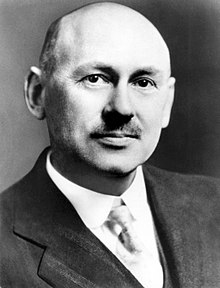
Despite the incredible amount of overblown hype, VASIMR is an incredibly interesting design. Dr. Franklin Chang Diaz, the founder of Ad Astra Rocket Company, became interested in the concept while he was a PhD candidate at MIT for applied plasma physics. Before he was able to pursue this concept, though, his obsession with space led him to become an astronaut, and he flew seven times on the Space Transport System (Space Shuttle), spending a total of over 66 days on orbit. Upon retiring from NASA, he founded the Ad Astra Rocket Company to pursue the idea that had captured his imagination during his doctoral thesis; refined by his understanding of aerospace engineering and propulsion from his time at NASA. Ad Astra continues to develop the VASIMR thruster, and consistently meets its deadlines and budgetary requirements (as well as the modeling expectations of Ad Astra), but the concept is complex in application, and as with everything in aerospace, the development process takes a long time to come to fruition.

After the end of several rounds of funding from NASA, and a series of successful tests of their VX-100 prototype, Ad Astra continued to develop the thruster privately. Their newer VX-200 thruster is designed for higher power, and with better optimization of several of its components. Following additional testing, the engine is currently going through another round of upgrades to prepare for a 100-hour test firing of the thruster. Ad Astra has been criticized for its development schedule, and the problems that they face are indeed significant, but so far they’ve managed to meet every target that they’ve set.
The main advantage of this concept is that it eliminates both friction and erosion between the propellant and the body of the thruster. This also reduces the thermal load on the thruster, because, since there’s no physical contact, conduction can’t occur, and the amount of heat that’s absorbed by the thruster is limited to radiation (which is limited by the surface area of the plasma and the temperature difference between that plasma and the thruster body). This doesn’t mean that there’s not a need to cool the thruster in most cases, it does mean that more heat is kept within the plasma, and in fact, by using regenerative cooling (as most modern chemical engines do) it’s possible to increase the efficiency of the thruster.
Another major advantage, and one that may be unique to VASIMR, is the first part of the acronym: VAriable Specific Impulse. Every staged rocket has variable specific impulse, in a way: most first-stage boosters have very low specific impulse compared to the upper stages (although, in the case of the boosters, this is due to both the atmospheric pressure and the need to impart a large amount of thrust over a limited timespan), and there are designs that use different propulsion systems with different specific impulse and thrust characteristics to optimize their usefulness for particular mission profiles (such as bimodal thermal-electric nuclear rockets, the subject of our next blog series after our look at electric propulsion), but VASIMR offers the ability to vary its’ exhaust velocity by changing the temperature it heats the propellant to. This, in turn, changes the specific impulse, and therefore its’ thrust. This is where the “30 Day Round Trip to Mars” clickbait headlines come into play: by continuously varying its’ thrust and isp depending on where it is in terms of the interplanetary transfer maneuver, VASIMR is able to optimize the trip time in ways that few, if any, other contemporary propulsion types can. However, the trip time is highly dependent on available power, and trip times on the order of 90 days require a power source of 200 MW, and the specific power of the system becomes a major concern. To explain this in detail gets into orbital mechanics far more deeply than I would like in this already very long blog post, so we’ll save that discussion for another time.
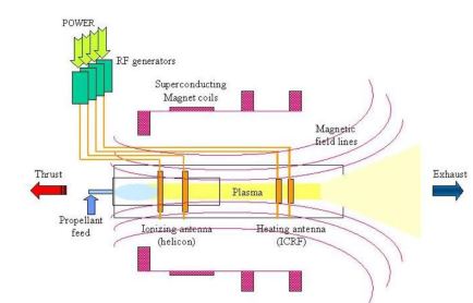
So how does VASIMR actually work, what are the requirements for efficient operation, and how does it have these highly unusual capabilities? In many ways, this is very similar to a typical RF thruster: a gas, usually argon, is injected into a quartz plenum, and then run through a helicon RF emitter. Because of the shape of the radio waves produced, this causes a cascading ionization effect within the gas, converting it into a plasma, but the electrons aren’t removed, like in the case of more familiar electrostatic thrusters (the focus of our next blog post). This excitation also heats the plasma to about 5800K. The plasma then moves to a second RF emitter, designed to heat the plasma further using an ion cyclotron emitter. This type of RF emitter efficiently heats the plasma to the desired temperature, which is then directed out of the back of the thruster. Because all of this is occurring at very high temperatures, the entire thruster is wrapped in superconducting electromagnets to contain the plasma away from the walls of the thruster, and the nozzle used to direct the thrust is magnetic as well. Because there are no components physically in contact with the plasma after it becomes ionized, there are no erosion wear points within the thruster, which extends the lifetime of the system. By varying the amount of gas that is fed into the system while maintaining the same power level, the gas will become ionized to different levels, and the amount of heating that occurs will be different, meaning that the exhaust velocity will be higher, increasing the specific impulse of the engine while reducing the thrust. This is perhaps the most interesting part of this propulsion concept, and the reason that it gets so much attention. Other systems that use pulsed thrust rather than steady state are able to vary the thrust level without changing the isp (such as the pulsed induction thruster, or PIT) by changing the pulse rate of the system, but these systems have limits as to how much the pulse rate can be varied. We’ll look at these differences more in a later blog post, though.

Many studies have looked at the thrust efficiency of the VASIMR. Like many electric propulsion concepts, it becomes more efficient as more power is applied to the system; in addition, the higher the specific impulse being used, the more efficiently it uses the electrical power available. The current VX-200 prototype is a 212 kW input, 120 kW thrust system, far more powerful than the original VX-10, and as such is more efficient. Most estimates of average efficiency seem to suggest a minimum of 60% thrust efficiency (the amount of efficiency increases with power input), increasing to 90% for higher-isp functioning. However, given the system’s sensitivity to available power level, and the fact that it’s not clear what the final flight thruster’s power availability will be, it’s difficult to guess what a flight system’s thrust efficiency will be.
VASIMR is currently upgrading their VX-200 thruster for extended operations. As of this point, problems with cooling various components (such as the superconducting electromagnets) have led to shorter lifetimes than are theoretically possible, although to be fair the lack of cooling problems come down to cooling systems not being installed. Additionally, more optimization is being done on the magnetic nozzle. One of the challenges with using a magnetic nozzle is that the plasma doesn’t want to “unstick” from the magnetic field lines used to contain the propellant. While this isn’t a major challenge for the thruster the way that the thermal management problems are, it is a source of inefficiency in the system, and so is worth addressing.
There’s a lot more that we could go into on VASIMR, and in the future we will come back to this concept; but, for the purposes of this article, it’s a wonderful example of how gray the area between thermal and MPD thrusters are: the propellant ionization and magnetic confinement of the heated plasma are both virtually identical to the applied field MPD thruster (more on that below), but the heating mechanism and thrust production are virtually identical to an RF thruster.
Let’s go ahead and look at what happens if you use magnetic fields instead of heat to accelerate your propellant, but keep most of the systems we’ve described identical in function: the magnetoplasmadynamic thruster.
Magnetoplasmadynamic Thrusters
Coauthor: Roland A. Gabrielli, IRS

Magnetoplasmadynamic thrusters are a high-performance electric propulsion concept; and, as such, offer greater thrust potential than the electrostatic thrusters that we’ll look at in the next blog post. They also tend to have higher power requirements. Therefore they have not been used as a dedicated thruster on operational spacecraft to date, although they’ve been researched since the 1960s in the USSR, the USA, Western Germany, Italy, and Japan. Only a few demonstrators have flown on both Russian and Japanese experimental satellites. They remain an attractive and cost efficient option for high-thrust electric propulsion including Mars transfer engines.
So far in this article, we have discussed electric thrusters which are principally thermal thrusters: The propellant runs into a reaction chamber, tanks heat and expands through a nozzle. This is as true for VASIMR, resistojets, thrusters based on inductive plasma generators, and also for arcjets. Yet, VASIMR introduces a different set of physics for thrusters, magnetohydrodynamics (MHD). This term designates the harnessing of fluids (hence ‘hydro’) with the forces (hence ‘dynamic’) emerging from magnetic fields (hence ‘magneto’). In order to effectively use magnetic forces, the fluid has to be susceptible to them, and its particles should somehow be electrically polar or even charged. The latter case, plasma, is the most common in electric propulsion.
Since the characteristics of plasma did not play a vital role in the working principles of the previous thermo-electric thrusters, we should briefly discuss the concept. The energy of plasma is so high that electrons are no longer tied to their atoms, which then become ions. Both electrons and ions are charged particles whizzing around in a shared cloud, the plasma. Despite being neutral to the outward due to containing the same amount of negative as of positive charges, the plasma interacts with magnetic fields. These magnetohydrodynamic interactions present themselves for various applications, ranging from power generators in terrestrial power plants over magnetic plasma bottles to propulsion.
In VASIMR, these forces push the hot plasma away from the walls, protecting both the walls from damaging heat loads and the plasma from cooling so rapidly that thrust is lost. This allows VASIMR to have a very hot medium for expansion. While this puts VASIMR among MHD thrusters, it would not yet be a genuine “plasma thruster,” if it was not for the magnetic nozzle, which adds electromagnetic components to the forces generating the thrust. Among these components, the most important is the Lorentz-force, which occurs when a charged particle moves through a magnetic field. The Lorentz-force is at right angles to both the local magnetic field line as well as to the particle’s trajectory.
There are two main characteristics of an MPD thruster:
- The plasma constitutes a substantial part of the medium, which imparts a significant integral Lorentz force,
- the integral Lorentz force has a relevant contribution towards the exhaust direction.
The electromagnetic contribution is the real distinction from the previous thermal approaches, as the kinetic energy of the jet is not only gained from undirected heating, but also from a very directed acceleration. The greater the electric discharge, and the more powerful the magnetic field, the more the propellant is accelerated, therefore the more the exhaust velocity is increased. Besides the Lorentz force, there are also minor electromagnetic effects, like a “swirl” and Hall acceleration (which will be looked at in the next blog post), but the defining electromagnetic contribution of MPD thrusters is the Lorentz force. Since the latter applies on a plasma, this type of thrusters is called magnetoplasmadynamic (MPD) thrusters.
The Lorentz force contribution is also the way magnetic nozzles work:the forces involved can be broken into three parts: along the thruster axis, toward the thruster axis, and at right angle to both of these around the axis. The first part adds to the thrust, the second pushes the plasma towards to the centre, the third generates a swirling effect, both contributing to the thrust as to spreading the arc into a radial symmetry.

There are various ways to build MPD thrusters, with differing different propellants, geometries, methods of plasma and magnetic field generation, and operation regimes, stationary or pulsed. The actual design depends mostly on the available power. The core of the most common architecture for stationary MPD thrusters is the arc plasma generator, which makes MPD thrusters seem fairly similar to thermal arcjets. But that’s just in appearance, as you can in fact build MPD thrusters almost completely free of a thermal contribution to the thrust, as evidenced by the German Aerospace Center’s (DLR) X-16, or the PEGASUS thruster that we’ll look at later in this post.
These types of thruster (technically known as stationary MPD thrusters with arc generation) differ most noticeably is the way the magnetic field is generated:
- Applied-field (AF) MPD thrusters, endowed with either and torus of permanent magnets, or a Helmholtz coil placed around the jet.
- Self-field (SF) MPD thrusters, which generate their magnetic field by induction around the current travelling in the arc.
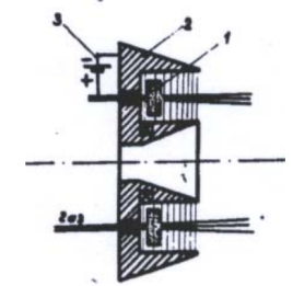
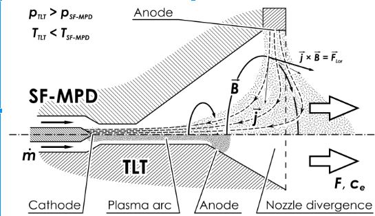
Note that arc generator based AF-MPD thrusters also experience (to a minor extent) self-field effects. A schematic of an SF-MPD thruster is shown below, illustrating the conceptual differences between arcjets, and MPD thrusters (the top half is an MPD, the bottom half is an arcjet, note the difference in throst length and nozzle size). The most crucial difference is the contact of the arc with the anode. While a very long arc is undesirable in arcjets (for very important design reasons which we don’t have time to go into here), in the MPD thruster this is crucial to provide the thruster with sufficient Lorentz force. Moreover, the longer the oblique leg of the arc, the more of the Lorentz force will point out of the thruster. This effect means that relatively large anode diameters are the norm with MPD thrusters of this type. Therefore, simple arcjets and other electro-thermal thrusters tend to be more slender than most arc based MPD thrusters. The anode diameter may however not be too large, as the arc will be more resistive with increasing lengths, entailing more and more energy losses.
In stationary arc based MPD thrusters, the choice of propellant is mainly dictated by the ease of ionisation which tends to be more important than molar mass, which is what causes the preference for hydrogen in thermal thrusters. This shift is the more pronounced, the more the Lorentz-force contribution outweighs the thermal contribution. Consequently, many arc based MPD experiments are run with noble gasses, like Helium, or Neon; while Xenon is often discussed in pure development, it is rarely considered for missions due to its cost. The most important noble gas for MPD is thus Argon. Other easily ionised substances are liquid alkali metals, commonly Lithium, which enables very good efficiencies. However, the complicated propellant feed system and the risk of depositions in that case is a serious drawback. Nevertheless, there is still a very large field for hydrogen or ammonia as propellants.
The major lifetime restricting component in arc based MPD are the cathode and – to a minor extent – anode lifetimes. These will erode over time which is caused by the plasma arc. The arc will gnaw at the metals due to electron emission, sublimation and other mechanisms. Depending on the quality of the design and the material, this will be significant after a few hundred hours of operation, or a tens of thousands. Extending their life is a challenge, because the plasma behavior will change depending on a number of factors determined by the plasma and the system in question. To add to the complexity, the geometry of the electrodes, affected by the erosion, is one of them. Because of this, some designs have easily replaceable cathodes, others (like the Pegasus which we’ll cover below) just swap out the drive: the original design for the SEI that Pegasus was proposed for actually had seven thrusters on board, run in series as the cathode wore out on each one.
AF-MPD – The Lower-Power Option

Depending on the available power, the arc current in MPD may or may not be intense enough to induce a significant magnetic self-field. At the lower end of the power scale, this is definitely breaking the MPD thruster principle. Because of this, in lower powered systems an external magnet is required to create the magnetic field, which is why it’s called an applied field MPD. In general, these systems range from 50 to 500 kW of electric power, although this is far from a hard limit. The advantage of applied field MPD thrusters over a self-field types (more on the self-field later) is that the magnetic fields can be manipulated independent of the amount of charge running through the cathode and anode, which can mean longer component life for the thruster. There are two main approaches to provide for an external field: The first is a ring of a permanent magnet around the volume occupied by the arc; the second is the placement of a Helmholtz coil instead (an electromagnet whose coil wraps around the lengthwise axis of the thruster, sometimes using superconductors). At the lower ending of the power range, the permanent magnet may be the better option because it doesn’t consume what little electricity you have, while the electromagnets are more interesting at the upper end.
All these solutions do require cooling, and the requirements are important the more powerful the magnet is. This cooling can be achieved passively at the lower ending of the power range (given enough free volume). For mid level power, the cold propellant itself can provide the cooling prior to running alongside the hot anode and entering the plasma generator. Using cold propellant for cooling the thrusters is called regenerative cooling (a mainstay of current chemical and nuclear thermal engines). The most performant magnets for AF-MPD, superconducting coils, must be brought to really low temperatures, and this tends to require an additional, secondary coolant cycle, including an own refrigeration system, with pumps, compressors, and radiators.

The nice thing about the electromagnets is that it’s possible to tune the strength of the field in a certain range. If the coil degrades over time, more electricity (and coolant, due to increased electrical resistance) can be pumped through. This isn’t an option for a permanent magnet. However, the magnetic field generation equipment is one of the lifetime limiting components of this type of thruster, so it’s worth considering.
There’s not really a limit to how much power you use in an applied field MPD thruster, and especially with a Helmholtz coil you can theoretically tune your drive system in a number of interesting ways, like increasing the strength to constrict the plasma more if there’s a lower-mass stream. Something happens once the plasma has enough charge going through it, though: the unavoidable self field contribution increases. . Besides increasing the complexity of the determination of the field topology, the self field is an advantage. At sufficient power, you can get away without coil or magnets, making the system lighter, simpler, and less temperature-sensitive. This is why most very high powered systems use the self-field type of MPD.
Before we look at this concept in the next subsection, let us have a look at current developments from over the world. Table ## summarises a few interesting AF-MPD thrusters, both the performance parameters thrust F, exhaust velocity c_e, thrust efficiency η_T, electric (feed) power P_e and jet power P_T, and design, like anode radius r_A, cathode radius r_C, arc current I, magnetic field B and the propellant. Recent AF-MPD-thruster development was conducted by Myers in the USA, by MAI (the Moscow Aviation Institute) in Russia, at the University of Tokyo in Japan, and SX 3 in Germany at the Institute of Space Systems, Stuttgart. The types X 9 and X 16 in table ## are the IRS’ legacy from the German Aerospace Center (X 9, X 16).
| Thruster | Pro- pellant |
r_A / mm | r_C / mm | I / A | B / T | F / mN | c_e/ km/s | η_T / % | P_e / kW | P_T / kW |
| Myers | Ar | 25 | 6.4 | 1000 | 0.12 | 1400 | 14 | 22 | 44.5 | 9.8 |
| MAI | Li | 80 | 22.5 | 1800 | 0.09 | 2720 | 33.6 | 44.1 | 103.5 | 45.7 |
| U Tokyo | H2 | 40? | 4 | 200 | 0.1 | 50 | 55.6 | 19.3 | 7.2 | 1.4 |
| SX 3 | Ar | 43 | 6 | 450 | 0.4 | 2270 | 37.9 | 58 | 74 | 42.9 |
| X 16 | Ar | 20 | 3 | 80 | 0.6 | 251 | 35.9 | 38.8 | 11.6 | 4.5 |
| X 16 | Xe | 20 | 3 | 80 | 0.6 | 226 | 25.1 | 29.6 | 9.6 | 2.84 |
| X 9 | Ar | 20 | 5 | 1200 | 0.17 | 2500 | 20.8 | 28.1 | 93 | 26.1 |
Design parameters and experimental performance data from various AF-MPD thrusters from over the world. Gabrielli 2018


Self-Field MPD: When Power Isn’t a Problem
In the previous section, we looked at low and medium powered MPD thrusters. At those power levels, an external field had to be applied to ensure a powerful enough magnetic field is applied to the plasma to generate the Lorentz force. Even though it wasn’t enough to impart enough thrust, there was always a self field contribution, albeit a weak, almost negligible one. The cause of the self field contribution is the induction of a magnetic field around the arc due to the current carried. You can get an idea of the direction of a magnetic field with the “right fist rule” by closing your right fist around the generating current, with your thumb pointing towards the cathode. Your fingers will then curl in the direction of the magnetic field. To get the direction of the Lorentz force, all you have to do in the next step is aligning your right hand again. This time, your thumb has to point in the direction of the magnetic field, and – at right angle – your index finger into the direction of the current. At right angle to both fingers, the middle finger will point in the direction of the Lorentz-force. (Note that you can also use the latter three-fingers-rule to study the acceleration in AF-MPD thrusters.)
The strength of the induced self field will depend on the current. The stronger the current is, the stronger the magnetic field will be, and, in turn, the Lorentz acceleration. As a consequence, given a sufficient current, the self field will be effective enough to provide for a decent Lorentz acceleration.
The current depends on the available electric power put into the arc generator, making the applied field obsolete from certain power levels up. This reduces complications arising from using an external magnet, and provides good efficiencies and attractive performance parameters. For example, at 300 kWe, and with an arc current of almost 5 kA (compare to AF-MPDs currents ranging from 50 A to 2 kA) DT2, an SF-MPD thruster developed at the Institute of Space Systems in Stuttgart, can provide a thrust of approximately 10 N at an exhaust velocity of 12 km/s, with a thrust efficiency of 20%. The performance possibilities have many people considering the technology as a key technology for rapid, man rated interplanetary transport, in particular to Mars. In this use case, SF-MPD thrusters may even be competitive with VASIMR, weighing possible shortcomings in efficiency up with a significantly simpler construction and, hence, much smaller cost. However, lacking current astronuclear sources of sufficient power, the development is stagnant, and awaiting disruption on the power source side.


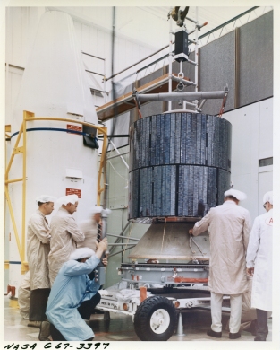
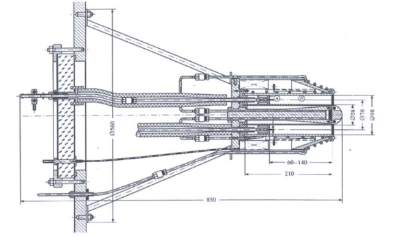
Another example of a “typical” self-field high powered MPD thruster application (since, like all types of electric propulsion, the amount of power applied to the thruster defines the operational parameters) is that seen in the PEGASUS drive, an electric propulsion system developed for the Space Exploration Initiative (SEI) for an electric propulsion mission to Mars. Committed research on this concept began in the mid-1980s, and was meant for a mission in the late-1990s to early 2000s, but funding for SEI was canceled, and the development has been on hold ever since. Perhaps the most notable is the shape, which is fairly typical of nozzles designed for a concept we discussed briefly earlier in the post: the sinuous curvature of the nozzle profile is designed to minimize the amount of thermal heating that occurs within the plasma, so if a nozzle has this shape it means that the thermal contribution to the thrust is not only not needed, but is detrimental to the performance of the thruster.

A number of novel technologies were used in this design, and as such we’ll look at it again a couple of times during this series: first for the thruster, then for its power conversion system, and finally for its heat rejection system.

Pulsed Inductive Thrusters
Pulsed inductive thrusters (PIT) are a type of thruster that has many advantages over other MPD thrusters. The thrusters don’t need an electrode, which is one of the major causes of wear in most thrusters, and they also are able to maintain their specific impulse over a wide range of power levels. This is because the thruster isn’t a steady-state thruster, like many other forms of thruster that are commonly in use; instead a gaseous propellant is sprayed in brief jets onto a flat induction coil, which is then discharged for a very brief period from a bank of capacitors (usually in the nanosecond range), causing the gas to become ionized and then accelerated through the Lorentz force. The frequency of pulses is dependent on the time it takes to charge the capacitors, so the more power that is available, the faster the pulses can be discharged. This directly affects the amount of thrust that’s available from the thruster, but since the discharges and volume of gas are all the same, the Lorentz force applied – and therefore the exhaust velocity of the propellant and the isp – remain the same. Another advantage of the inductive plasma generation is the wide variety of propellants available, from water to ammonia to hydrazine, making it attractive for possible in-situ propellant use with minimal processing. In fact, one proposal by Kurt Polzin at Marshall SFC uses the Martian atmosphere for propellant, making refueling a Mars-bound interplanetary spacecraft a much easier proposition.

This gives a lot of flexibility to the system, especially for interplanetary missions, because additional thrust has distinct advantages when escaping a gravity well (such as Earth orbit), or orbital capture, but isn’t necessary for the “cruise” phase of interplanetary missions. Another nice thing about it is, for missions that are power-constrained, many thruster types have variation in specific impulse, and therefore the amount of propellant needed for the mission, depending on the amount of power available for propulsion when combined with other electricity requirements, like sensors and communications. For the PIT, this just means less thrust per unit time, while the isp remains the same. This isn’t necessarily a major advantage in all mission types, but for some it could be a significant draw.
PIT was one of the proposed propulsion types for Project Prometheus (which ended up using the HiPEP system that we’ll discuss in the next blog post), known as NuPIT. This thruster offered thrust efficiency of greater than 70%, and an isp of between 2,000-9,000 seconds, depending on the specific design that was decided upon (the isp would remain constant for whatever value was selected), using a 200 kWe nuclear power plant (which is on the lower end of what a crewed NEP mission would use), with ammonia propellant. Other propellants could have been selected, but they would have affected the performance of the thruster in different ways. An advantage to the PIT, though, is that its breadth of propellant options are far wider than most other thruster types, even thermal rockets, because if there’s chemical dissociation (which occurs to a certain degree in most propellants), anything that would become a solid doesn’t really have a surface to deposit onto effectively, and what little residue builds up is on a flat surface that doesn’t rely on thermal conductance or orifice size for its’ functionality, it’s just a plate to hold the inductive coil.

For a “live off the land” approach to propellant, PIT thrusters offer many advantages in their flexibility (assuming replacement of the gaseous diffuser used for the gas pulses), predictable (and fairly high) specific impulse, and variable thrust. This makes them incredibly attractive for many mission types. As higher powered electrical systems become available, they may become a popular option for many mission applications.
We’ll return to PIT thrusters in a future post, to explore the implications of the variable thrust levels on mission planning, because that’s a very different topic than just propulsion mechanics. It does open fascinating possibilities for unique mission profiles, though, in some ways very similar to the VASIMR drive.
More to follow!
Thermo-electric and MPD thrusters cover a wide range of low to high power thruster options, and offer many unique capabilities for mission planners and spacecraft architects. With the future availability of dense, high-powered fission power systems for spacecraft, these systems may show that they offer unique capabilities, not just for short missions or reaction control systems, but also for interplanetary missions as well. Some will need to wait until these power sources are available to be used, but others are already in use on operational satellites, and have shown dozens of years of efficient and effective operation.
The next post will complete our look at electric propulsion systems with a look at electrostatic thrusters, including gridded ion drives, Hall effect thrusters, and other forms of electric propulsion that use differences in electric potential to accelerate an ionized propellant. These have been in use for a long time, and are far more familiar to many people, but there are some incredible designs that have yet to be flown that extend the capabilities of these systems beyond even the very efficient systems in use today.
Another thank you to Roland Gabrielli and Mikkel Haaheim for their invaluable help on this blog post. Without them, this wouldn’t be able to be nearly as comprehensive or accurate as it is.
Again, I apologize that this blog post has taken so long. Unfortunately, I reached the point that I typically decide to split one blog post into two several times in this post, and actually DID split it a couple times. Much of this information, as well as a lot of it from the next post on electrostatic thrusters, was originally going to be part of the last post, but once that one reached 25 pages in length I decided to split it between history and summary, and this occurred once again in writing this post, separating the electrostatic thrusters from the thermal and MPD thrusters. The latter two concepts also almost got their own blog posts, but as we’ve seen, the two share key features and so it made sense to keep them together. The electrostatic thruster post is already coming along well, and I hope that it won’t take as long for me to write as this one did… sadly, I can’t promise that, but I’m trying.
Sources
Electrothermal
An Analysis of Current Propulsion Systems, Weebly website http://currentpropulsionsystems.weebly.com/electrothermal-propulsion-systems.html
Resistojet
Vela spacecraft, Gunters’ Space Page profile https://space.skyrocket.de/doc_sdat/vela.htm
Alta Space Systems Resistojet page: https://web.archive.org/web/20130604101644/http://www.alta-space.com/index.php?page=resistojet
Induction Thermal Thruster
Microwave/RF Thermal Thruster
Coaxial Microwave Electrothermal Thruster Performance in Hydrogen, Richardson et al, Michigan State 1968 https://ntrs.nasa.gov/archive/nasa/casi.ntrs.nasa.gov/19950005171.pdf
Microwave Electrothermal Thruster webpage, Princeton http://alfven.princeton.edu/research/past/met
The Microwave Thermal Thruster Concept, Parkin et al, CalTech https://authors.library.caltech.edu/3304/1/PARaipcp04b.pdf
Microwave Electro-thermal Thruster patent, Rayethon 1999 https://patents.google.com/patent/US5956938
Fourth Symposium on Beamed Energy Propulsion, ed. Komurasaki and Yabe, 2005 https://sciencedocbox.com/Physics/70705799-Beamed-energy-propulsion.html
Arcjet
Arc-Jet Thruster for Space Propulsion, Wallner et al 1965 https://ntrs.nasa.gov/archive/nasa/casi.ntrs.nasa.gov/19650017046.pdf
Aerojet MR-510 hydrazine arcjet page, Astronautix: http://www.astronautix.com/m/mr-510.html
University of Stuttgart ISS PTFE PFTE Arcjet Mission concept webpage: https://web.archive.org/web/20140318021932/
http://www.elringklinger.de/en/germany-land-of-ideas-elringklinger-drives-satellite
VASIMR
High Power Electric Propulsion with VASIMR Technology, Chiand-Diaz et al 2016
http://www.unoosa.org/documents/pdf/psa/hsti/CostaRica2016/2-4.pdf
VX-200 Magnetoplasma Thruter Performance Results Exceeding 50% Thruster Efficiency, Longmier et al 2011 https://www.researchgate.net/publication/228977378_VX-200_Magnetoplasma_Thruster_Performance_Results_Exceeding_Fifty-Percent_Thruster_Efficiency
Improved Efficiency and Throttling Range of the VX-200 Magnetoplasma Thruster, Longmier et al 2014 http://www.adastrarocket.com/Ben-JPP-2014.pdf
Low Thrust Trajectory Analysis (A Survey of Missions using VASIMR For Flexible Space Exploration, Ilin et al 2012 http://www.adastrarocket.com/VASIMR_for_flexible_space_exploration-2012.pdf
Nuclear Electric Propulsion Mission Scenarios using VASIMR, Chiang-Diaz et al 2012 https://www.lpi.usra.edu/meetings/nets2012/pdf/3091.pdf
MPD
Steady State MPD
Magnetic Nozzle Design for High-Power MPD Thrusters, Hoyt Tethers, Unlimited 2005 http://www.tethers.com/papers/IEPC05_HoytNozzlePaper.pdf
Applied Field MPD
Applied-Field MPD Thruster Geometry Effects, Myers Sverdup 1991 https://ntrs.nasa.gov/archive/nasa/casi.ntrs.nasa.gov/19910017903.pdf
Performance of an Applied Field MPD Thruster, Paganucci et al 2001 http://erps.spacegrant.org/uploads/images/images/iepc_articledownload_1988-2007/2001index/2002iepc/papers/t12/132_2.pdf
Mayer, T., Gabrielli, R. A., Boxberger, A., Herdrich, G., and Petkow, D.,: “Development of Analytical Scaling Models for Applied Field Magnetoplasmadynamic Thrusters,” 64th International Astronautical Congress, International Astronautical Federation, Beijing, September 2013.
Myers, R. M., “Geometric Scaling of Applied-Field Magnetoplasmadynamic Thrusters,” Journal of Propulsion and Power, Vol. 11, No. 2, 1995, pages 343–350.
Tikhonov, V. B., Semenikhin S. A., Brophy J.R., and Polk J.E., “Performance of 130 kW MPD Thruster with an External Magnetic Field and Li as a Propellant”, International Electric Propulsion Conference, IEPC 97-117, Cleveland, Ohio, 1997, pp. 728-733.
Boxberger, A., et al.. “Experimental Investigation of Steady-State Applied-Field Magnetoplasmadynamic Thrusters at Institute of Space Systems”, 48th AIAA/ASME/SAE/ASEE Joint Propulsion Conference & Exhibit, Atlanta, Georgia, 2012.
Boxberger, A., and G. Herdrich. “Integral Measurements of 100 kW Class Steady State Applied-Field Magnetoplasmadynamic Thruster SX3 and Perspectives of AF-MPD Technology.” 35th International Electric Propulsion Conference. 2017.
Pegasus Drive
The Pegasus Drive: A Nuclear Electric Propulsion System for the Space Exploration Initiative; Coomes and Dagle, PNL 1990 https://www.osti.gov/servlets/purl/6399282
A Low-Alpha Nuclear Electric Propulsion System for Lunar and Mars Missions; Coomes and Dagle, PNL 1992 https://www.osti.gov/servlets/purl/10116111
MPD Thruster Performance Analysis Models; Gilland and Johnson NASA GRC, 2007 https://ntrs.nasa.gov/archive/nasa/casi.ntrs.nasa.gov/20070032052.pdf
Self-Field MPD
On the Thrust of Self-Field MPD Thrusters, Choueiri 1997 https://alfven.princeton.edu/publications/choueiri-iepc-1997-121
Pulsed Inductive Thruster (PIT)
The PIT Mark V Pulsed Inductive Thruster, Dailey et al 1993 https://ntrs.nasa.gov/archive/nasa/casi.ntrs.nasa.gov/19930023164.pdf
The Nuclear Electric Pulsed Inductive Thruster (NuPIT) Mission Analysis for Prometheus, Frisbee et al 2005 https://trs.jpl.nasa.gov/bitstream/handle/2014/38357/05-1846.pdf
Pulsed Inductive Thruster Using Martian Atmosphere as Propellant, Polzin 2012 https://ntrs.nasa.gov/archive/nasa/casi.ntrs.nasa.gov/20120015307.pdf