Electric propulsion is often seen to be the future of in-space propulsion. There are many different methods of using electricity to propel a spacecraft, which we’ll briefly look at on this page. However, each section also links to a more in-depth look at each specific type of electric thruster, as well as some designs for higher-powered thrusters that can be used in conjunction with a nuclear reactor to propel a nuclear electric spacecraft.
This is a summary of the general types of electric propulsion that we’ve covered on Beyond NERVA. We did a series of blog posts on the web page, but the sheer number of information about the different concepts, designs, and possibilities led to long (and sometimes difficult to digest) posts. This page is a summary of the general types of electric propulsion available, to highlight the different options, with their general strengths and weaknesses. Click on the title of each section, or the link at the end of each section, to visit the page for each type of thruster, including examples of high-power designs that may be suitable for nuclear electric spacecraft.
The original blog posts can be found here (however, if you’re interested in a shorter, easily-digested overview, this page is a better option):
History of Electric Propulsion
Electric Propulsion Part 1: Electrothermal and Magnetoplasmadynamic Thrusters
Electric Propulsion Part 2: Electrostatic Propulsion
Why Electric Propulsion?
Unlike the generally higher thrust options that nuclear thermal rockets offer, nuclear electric propulsion offers low-thrust, but overall high change in velocity for given propellant and initial masses, by trading one or more large changes in velocity at the beginning and end of a mission, and instead using a slow-but-steady approach to provide even more total thrust, often over the entire length of the mission. Since each celestial body is orbiting the Sun at different speeds, distances, orbital eccentricities (how circular the orbit is), and even inclinations to a certain extent (how far above or below its’ orbit extends compared to Earth), there’s a certain amount of energy required to reach each destination, with spacecraft often using things like gravitational assist maneuvers (exchanging kinetic energy between the spacecraft and a body by performing a close fly-by of a planet) to get enough energy to meet their necessary change in velocity, known as their delta vee budget.
The most efficient forms of orbital maneuver are called Hohmann transfer orbits, which basically raise a spacecraft’s orbit around the Earth until it intersects the orbit of another planet, and then the spacecraft slows down to orbital velocity around that planet. This is how we got to the moon, how we get to Mars, and many other missions to other planets as well. It’s the least fuel-hungry way to get a mission to its’ destination, and this means more payload once it gets there. However, it’s also the slowest method of travelling interplanetary distances (other than the strictly theoretical notion of the “interplanetary” railroad, which works by riding the gravitational instabilities between planets); and often, with electric propulsion, this isn’t necessary.
Instead, once an electrically-propelled spacecraft reaches their minimum-needed delta vee budget, they keep firing their thrusters,adjusting their thrust vectors, until they gradually match their trajectory with that of the target. The shape of this orbit is going to be slightly different, the launch times are generally speaking somewhat more flexible, and the mission options available are generally higher. The total trip time is also usually lower than would be possible with either chemical or nuclear thermal rockets, if those would have even been able to make the trip at all, within the constraints of a given payload mass.
The reason electric propulsion can do what it does is because it generally has a high specific impulse (isp), or fuel efficiency. While chemical rockets are doing really well if they’re able to achieve 450 seconds (which can be considered a good analogue to fuel efficiency, although the technical details are slightly different), and nuclear thermal rockets can achieve between 950 and 1200 s of isp (some can theoretically go higher, but it requires more exotic concepts than we’ve looked at in the blog so far), electric propulsion generally ranges from 1500 s to over 14,000 s of specific impulse! This means that far less fuel is needed to provide the same amount of delta-vee for a mission.
The downside to electric propulsion is, rather than measuring thrust in megaNewtons, usually thrust from electric propulsion is measured in microNewtons. This makes leaving orbit under just electric propulsion (or changing your orbit around Earth) a much longer process than it is for chemical or thermal propulsion. Most of the time this is fine, and in the course of a mission to the outer solar system that time in orbit will be only a small part of the trip time, but it can mean that a spacecraft is still in Earth orbit for weeks (or months, in some cases) while it’s firing its thrusters to escape Earth orbit. This downside also comes into play if sudden maneuvers, such as avoiding orbital debris, are needed, so often smaller chemical reaction control systems are used, or less efficient but more powerful electric thrusters are used.
Electric propulsion can run off any power source available, assuming that the power is “conditioned,” meaning that the voltage, amperage, and amount and type of current has been matched to the thruster. Solar and radioisotope thermoelectric generators have both been used rather extensively for electric propulsion, but they both have a low specific power (the ratio of power output to mass) and large surface area (in the case of solar panels) compared to nuclear power plants; making them susceptible to damage, minute but significant amounts of thrust from light pressure and solar wind, and atmospheric drag, if they’re in Earth orbit (or any other planet with an atmosphere). Additionally, once megawatts of power are needed or desired, the total mass of a fission power plant is less than that of a solar power plant of the same output.
As a general rule of thumb, electric propulsion is great for either long-duration missions, where fuel supply is the factor that determines the lifetime of the mission, or for longer mission distances. For many missions to the outer solar system, the only option is electric propulsion, because the spacecraft wouldn’t be able to carry enough fuel to complete the mission if they were using chemical or thermal rockets. Even the different thrusters each have their advantages and disadvantages: electric thermal propulsion or Hall thrusters are generally speaking less efficient in terms of specific impulse than gridded ion thrusters; so, if the mission is in Earth orbit or to the Moon, the higher thrust from the first two might be better, but they’re unlikely to get you to Jupiter as well as a gridded ion thruster would. This is a large part of why electric propulsion systems, both already in-use and proposed, are so diverse: to meet different mission demands for different spacecraft.
Types of Electric Propulsion
Electric propulsion is an incredibly broad topic, as we’ve seen in the last couple blog posts. It’s been researched since the dawn of the space age, but it wasn’t until the 80s (in the Soviet Union) and 90s (in the US) that it became common. Today, it would not be an exaggeration to say that the majority of in-space propulsion on the majority of the currently operational satellites is provided by electric propulsion of one form or another. However, which system is used when is a very diverse topic, because of the advantages and disadvantages that each system has.
Each type of electric propulsion has a number of characteristics in common, though: high specific impulse, low thrust, respectable thrust efficiency (how efficient the thruster is at turning the electricity applied to the propellant into thrust)and overall efficiency (which takes into account not just the system that produces the thrust, but any associated equipment as well, such as electromagnets, propellant pumps, and other systems), and specific thrust (the amount of thrust produced for the mass of the thruster). In general, each of these factors are dependent on a number of things, including power level applied to the thruster, the type of propellant used, desired operational regime, and other factors. It’s difficult to make side-by-side comparisons of many of these types of systems, because they vary so widely. For instance, resistojets are commonly used for cubesat propulsion today, and so tend to be very small, very low power systems on the order of a few watts; while self-field MPD thrusters use dozens of kilowatts or more of power, and tend to be far larger.
Electrostatic Propulsion
Electrostatic propulsion uses electric potential differences between portions of a thruster and an ionized propellant to accelerate that propellant at high velocities. There are a number of different types of electrostatic thruster, but the main two are a gridded ion drive and the Hall effect thruster.
Gridded Ion Drives
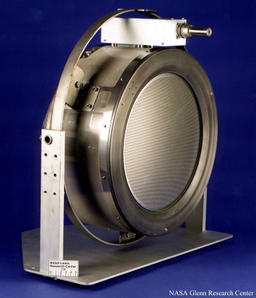
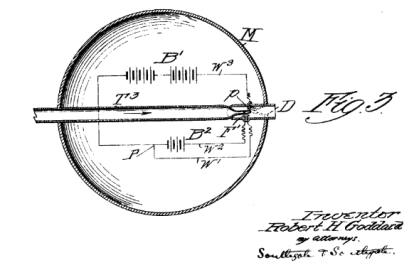
Perhaps the best known type of electric propulsion, the gridded ion drive has been used since the 1960s, but the modern incarnation of the concept started in the 1990s at NASA. These drives use an ionization chamber, which can use an electron gun, an RF resonant ionization system, or other mechanism to turn a gaseous propellant into a plasma. This is then separated from the non-ionized propellant with a pair of grids, then accelerated using a more strongly negatively charged screen. A cathode is then used to inject the electrons that had been stripped away from the propellant, so the resulting exhaust plume is a mostly-neutrally-charged stream of usually xenon; but argon, cesium, iodine, and other propellants have been used or proposed as well.
These types of thruster generally operate in the mN thrust range, and vary in power level from 500 W to several kW; but one distinct thing about them is that they tend to have very high isp, all the way to 14,000 s for the Dual Stage 4 Grid ion thruster developed by the Australian National University. Thruster efficiency tends to be in the 30-50% range, depending on the propellant used and the power level of the thruster.
To find out more about gridded ion drives, check out the Gridded Ion Propulsion page!
Hall Effect Thrusters

Hall effect thrusters (HET) use the Hall effect, which is a similar-in-result, but different physical mechanism to the Lorentz force. Here, the propellant is passed through an anode into a magnetic field. This causes some of the electrons to be stripped off their atoms, and rotate through the resulting gas. This further ionizes the propellant, which is accelerated out of the nozzle toward a negative electrical potential produced by a cathode, which is also ejecting electrons to neutralize the beam.


There are two variants of HETs, depending on the material used for the discharge chamber (where the propellant is ionized): Stationary Plasma Thrusters (SPTs) use an insulator, usually boron nitride, to line the propellant channel, and the distance between the anode and the cathode is much greater than in the second type; Thruster with Anode Layer (TAL) thrusters are much more shallow between the anode and the cathode; and rather than using an insulator to line the discharge channel, a conductor is used instead. Both types have been used on spacecraft; however, the SPT type tends to be for higher-power applications, while the TAL can be more efficient. The primary lifetime limitation on these thrusters is erosion of the discharge channel, so there is a lot of research that goes into improving materials for these channels to increase thruster life.
SPT type thrusters usually get between 1500 and 3000 s of isp, and have a thrust level in the range of 75-100 mN. Generally speaking, a single HET will use between 5 and 20 kW of electricity, although clusters of HETs have been proposed, as have variations in geometry. Overall thruster efficiencies vary widely depending on the type.
 One notable exception is the Very High Isp Thruster with Anode Layer, which is a 100 kW, dual stage TAL design: the first anode is used to ionize the propellant, while the second is used to accelerate it. This system also uses bismuth, which is an unusual choice for propellants. The advantage to this system is that it achieves up to 80% efficiency, with a thrust of 700 mN and a specific impulse of 8000 s! This is a very attractive system, if it continues to be developed.
For more information, check out the Hall Effect Thruster page!
Electric Thermal Propulsion
Thermal propulsion is the simplest in concept of all the electric propulsion systems, and also one of the most common. A source of heat, powered by an on-board electrical supply, heats a propellant (usually a gas), which passes out of a nozzle. The two most common ways to do this are either through resistive (or Ohmic) heating, much the same way a toaster or space heater works, or through arc heating, where a spark is used to heat the propellant; however, other designs use radio frequency or microwaves to heat propellant as well, and there are many variations on each of these types as well.
For more information on each of these thruster types, there’s a page on each. Just click the header of each section, or the link at the end of each description!
Resistojets
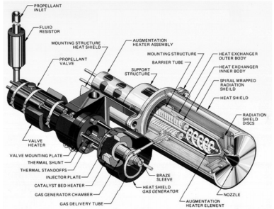 Resistively heated thrusters are often called resistojets. They have been used since the 1960s, but have made a resurgence in the smallsat and cubesat markets because they can use non-reactive propellants and be made extremely compactly. These thrusters, if using hydrazine propellant (a common choice for resistojets, since it decomposes), can achieve overall efficiencies of 90%, and a specific impulse of about 350 s, however most of these units are in the range of 3-10 mN of thrust due to their very small size. The primary limits of a resistojet are the melting point of the heating element, and how efficiently that heat can be transferred to the propellant while preventing overheating of the rest of the thruster. Thermal cycling of the thruster, through turning it on and off, is another major limitation to the lifetime of this type of thruster, because the heating element can break down over time. While they’re attractive options for on orbit operation, and possibly for cis-lunar missions, their low specific impulse makes it unlikely that interplanetary missions would use them as a main propulsion system. However, they may be used as a reaction control system on a spacecraft, due to their high thrust potential, simplicity in construction, and high thrust efficiency.
Check out the Resistojet page for more information!
Induction Thrusters
Induction heating, where a radio transmitter is used to heat a propellant, is another common option. Here, the propellant either needs to be partially ionized, or be a polar molecule (where the molecule itself has a north and south magnetic pole), which allows the radio waves to cause the molecules to move. This is a similar concept to what is found in a microwave or other RF heater, and has the advantage of not being thermally limited by the heating element found in resistojets.
Induction thrusters are generally speaking broken up into various types, based on the frequency of radio wave that’s being used to excite the propellant (which in turn is chosen based on the amount of power available, and which frequency of RF is being used). Inductive heating occurs usually between 100 and 500 kHz, radio frequency heaters for thrusters generally operate at 5-50 MHz, and microwave thrusters often operate above 500 MHz, although this can extend into the GHZ range. The main advantage of any type of RF (or other induction) thruster over other thermal propulsion concepts is that there aren’t any electrodes or heating elements needed, and since these are generally speaking the main lifetime and temperature limitations for a thermal thruster being able to eliminate them will improve thruster life and the temperature that the propellant can be heated to.
Induction thrusters are also structured differently from microwave and RF thrusters due to the shorter wavelength of the electromagnetic waves. While the other two often have a chamber where the propellant is heated, and the resulting pressure forces the propellant out of a nozzle, the most common form of induction thruster is the PIT, or pulsed induction thruster. One design built by TRW and tested at NASA used ammonia as a propellant to achieve between 3000 and 8000 s isp, at an overall efficiency of 50% when operating in the range of 14 kW.
RF thrusters can be more efficient than PIT thrusters, but generally also require higher power. Pure RF thermal thrusters are a rarity, partially because they’re better at ionizing the propellant rather than heating it, but in some cases they’re used for cubesats and nanosats. One example of this is the Pocket Rocket, under development at the Australian National University, which operated on 10 W of power using both N2 and Ar as propellants, which produced 2.4 mN of thrust at 76 s isp. However, higher power regimes could provide greater isp and thruster efficiency, the fact that this was designed for a very low power, compact application is a limitation of this particular design. Sadly, I was unable to find a pure RF thermal thruster any larger than this, due to the advantages that microwave heating offers over RF.
Microwave Thrusters
Microwave thrusters have also been studied since the 60s as a way to get around the thermal limitations of resistojets, and the electrode wear issues of an arcjet (more on those in a bit). One major focus of late has been using water as a propellant for a microwave thruster, since it’s inexpensive, mostly non-reactive, and has a high heat capacity. One recent design focusing on this concept, from the Florida Space Institute, operating at a range of 100 W to 50 kW, was able to demonstrate over 800 s isp, with a thrust efficiency of over 90%. PFTE, better known as Teflon, is another popular propellant for microwave thrusters, as is hydrogen, which has demonstrated a specific impulse of 1000 s and 54 kN of thrust in the 1970s. Some designs, such as DARPA’s Millimeter-wave Thermal Launch System, actually propose using a beam of microwaves from a fixed location, eliminating the need for the power plant to be on-board the spacecraft, however developing the beam controller for these systems has been a consistent challenge.
Check out the RF/Microwave thruster page for more information!
VASIMR
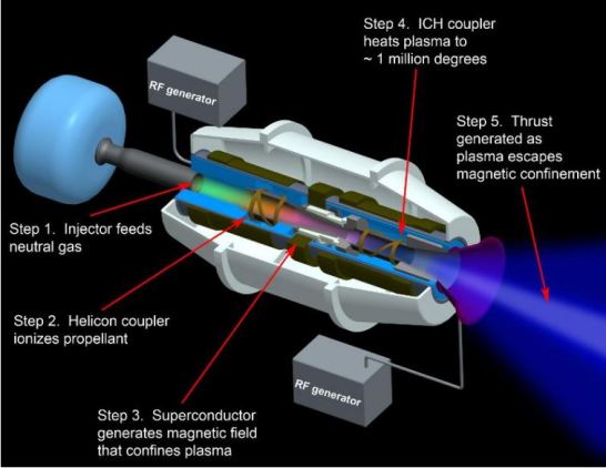
Perhaps the most famous type of microwave thermal thruster is the VASIMR drive (VAriable Specific Impulse Magnetoplasma Rocket), which is a unique configuration of RF thruster which uses magnetic containment to limit the amount of heat transferred from the propellant to the main body of the thruster. The RF cavity ionizes the propellant, which is then magnetically contained while it’s heated using a different frequency RF resonator, and then a magnetic nozzle is used to expel the propellant (often argon, but xenon and other propellants have been tested). As the name implies, this system varies its’ specific impulse to “change gears,” providing higher thrust or higher efficiency depending on the mode of operation. The current test-bed design for Ad Astra, the company developing the VASIMR, is a 200 kW design, and has demonstrated overall efficiency of over 60% (with a theoretical efficiency of up to 90%), and a theoretical isp from 0 s to over 30,000 s, however the company expects to limit the isp range of the engine to between 1500-2500 s to best optimize the drive capabilities for near-term use.
Since it’s so popular, VASIMR has its own page, which is available here!
Arcjets
The last form of electrothermal propulsion is the arcjet, which uses an electric arc to heat propellant and turn it into plasma, which is then ejected out of a nozzle. This type of thruster was also used in the 1950s, but didn’t become common until the 1990s. Various types of propellant can be used, including xenon, hydrogen, Teflon, and others. The advantage that arcjets offer is twofold: they’re very simple, and the spark between the cathode and anode can reach tens of thousands of degrees. Additionally, because of the design of most arcjets, any heating of the thruster body itself (which also serves as the anode) will pass its heat into the propellant itself, increasing the overall efficiency of the thruster. These systems tend to get between 350 s and 900 s of specific impulse, depending on the propellant used and the power level. However, they are also lifetime-limited by the wear of the cathode and anode, and certain designs, such as the ones that use a solid block of Teflon mounted on a spring mechanism, have other mechanical design issues as well.
The Gray Area Between Arcjets and Magnetoplasmadynamic Thrusters
Arcjets and the next type of thruster, the magnetoplasmadynamic, or MPD, thruster, can appear very similar. Many different types of MPD look very similar to an arcjet: they both use a pin-shaped cathode with an anode closer to the nozzle to generate current across the propellant, turning it into a plasma, they both have a throat immediately after the cathode, and they both are limited in their lifetimes by cathode and propellant throat wear.
This is an area that I wasn’t aware of until I started researching this subject, and one that I personally found fascinating. For a discussion of the similarities, and WHY they’re so similar, check out the discussion here!
Magnetoplasma Thrusters: Magnetically Driven Propulsion
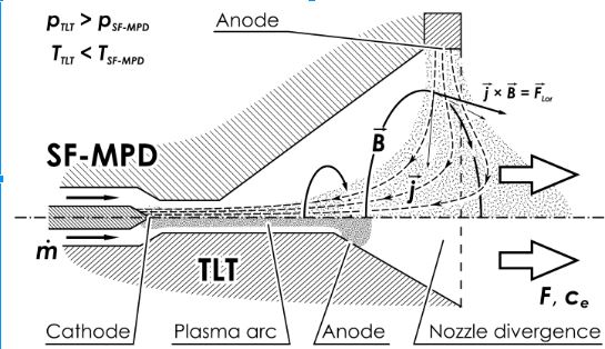
Magnetoplasmadynamic thrusters, or MPD thrusters, are often quite similar in structure to an arcjet, but instead of using thermal energy to accelerate their propellant, they use an electromagnetic phenomenon called the Lorentz force. This occurs when an electrical field and a magnetic field are perpendicular to each other, with the result that anything that’s got magnetic potential is pushed at right angles to both the electric and magnetic fields. Often, these designs avoid heating as much as possible, since it doesn’t actually contribute to the acceleration of the propellant. MPD thrusters come in two varieties, depending on the means of applying the magnetic field: applied field MPD uses magnets, either electromagnets or permanent magnets depending on the design, to cause the magnetic field, while self-field MPD uses the magnetic field inherent in the moving plasma to induce the Lorentz force. In general, applied field systems are lower power systems, while self-field really only becomes an option at higher power levels. As in arcjets, many of these designs are limited by the lifetime of the cathode and anode used to generate the electric field needed to accelerate the propellant.
AF-MPD designs have been demonstrated to get up to 45% thrust efficiency, 3700 s isp, and 2.27 N of thrust with 74 kW of power, but there’s a huge range in all of these characteristics depending on the design being studied. SF-MPD thruster designs operate in the hundreds of kWe range, and have been demonstrated to have thrust efficiencies in roughly the 20-30% range, with 1200 s isp and 10 N of thrust.
For more information about MPD thrusters, check out the MPD Thrusters page!
More Coming Soon!
Electric propulsion is an incredibly broad area, and one where overlooking a promising or interesting concept is easy to do. This page is going to continue to be updated over time, as more information becomes available (and I have time to write more on the subject). I hope to build a spreadsheet with the different thruster types, including the ideal mission types for each; this is a big project, though, so I’m not sure exactly when it’ll be ready. When it is, I’ll post a notification in the next blog post!
