The Nuclear Thermal Reactor Element Environmental Simulator was first proposed by William Emrich of NASA’s Marshall Spaceflight Center in 2008, and was designed to simulate everything but the radiation environment that an NTR fuel element would experience. This was the next best thing possible, short of starting nuclear hot-fire tests again (which neither the regulations nor the budget would allow): many of the other questions that needed to be answered in order to build a new NTR was being addressed in other programs: cryogenic hydrogen was a major challenge in Rover, but research had continued through chemical propulsion systems. Likewise the regeneratively cooled nozzle, which was a major manufacturing feat that often lead to headache in the 1970s was now routinely used, and better materials were available, too. The questions that remained mostly had to do with either core geometry or the fuel element itself, and most of those questions were chemical. By substituting other materials (such as ZrO2) with similar properties (thermal behavior, etc) to UO2 in initial tests, and then move on to the more difficult to use depleted uranium (DU) for more promising test runs (as we saw in the KRUSTY post, DU carries a far stricter burden as far as safety procedures ad regulation), testing could continue- and be more focused on the last details that needed to be worked out chemically and thermally.
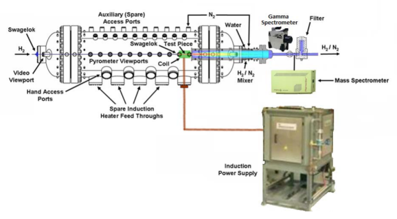
NTREES consists of a pressure vessel, an induction heating arrangement for the test article, a data acquisition unit, and an exhaust treatment system. Hydrogen is introduced at the needed pressure and rate into the pressure vessel, where it encounters the test article. Measurements are taken through view ports in the side of the pressure vessel, and then the hot hydrogen is cooled by adding a large amount of nitrogen. This gas mixture is then passed through a mass spectrometer, and then further cooled and collected. The mass spectrometer is designed to be able to detect a wide range of atomic masses, so that uranium-bearing compounds can be detected to measure fissile fuel erosion; with pressure, temperature, and flow sensors they make up the inputs for the data acquisition system.
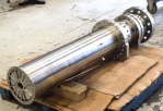
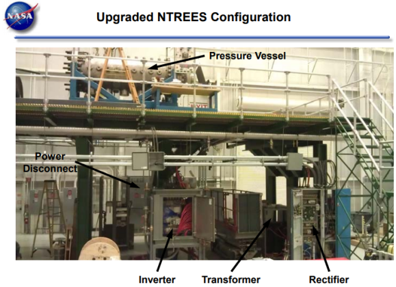
The bulk of the test stand is the pressure vessel, which is water cooled, ASME code stamped, and (at time of design) had a maximum operating pressure of 6.9 megapascals (MPa). When the test stand was being designed, flexibility was one of the main foci of the design decisions that were made; after all, new equipment for nuclear thermal testing is incredibly rare, and funding for it is virtually impossible to come by, so one piece of test equipment can’t be specialized to just one design, to sit collecting dust on the shelf after that project is canceled, especially if a new design comes along with requirements that make the old test equipment obsolete. As such, NTREES can handle test articles up to 2.5 meters in length, and 0.3 m in diameter. A number of sapphire view ports along each side of the pressure vessel are used for instrumentation (21 ports, 5.1 cm dia) and observation (9 ports with 7.1 cm diameter). Along the bottom are five ports for the induction heater used to bring the test article up to temperature (one of these can also be modified for vacuum system use).
The induction heater is a 1.2 MW unit installed during upgrades to the system in 2014, although the upgrade wasn’t immediately able to be fully implemented until later due to having to wait for funding to upgrade the N2 cooling system to handle the power increase.
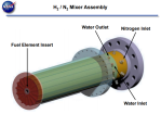
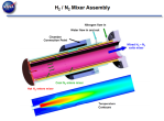
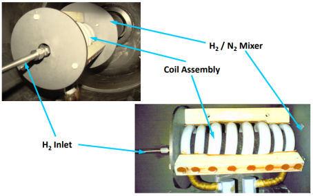
After the now-hot H2 leaves the test article, it enters a gas mixer, which adds cold nitrogen to cool the H2 rapidly, and to dilute it with a more inert gas to reduce explosive hazards. This sleeve is also water-cooled, which draws out even more heat from the gas. The lessons learned about handling gaseous and liquid hydrogen were well-learned, and multiple safety systems and design choices have gone into handling this potentially dangerous and reactive gas safely. Another example of this is at the hot end interface with the test article: there is more pressure on the nitrogen outside the H2 feed, so that N2 inbleeding prevents any H2 leakage at a seal which would be very prone to failure due to the high temperatures involved.
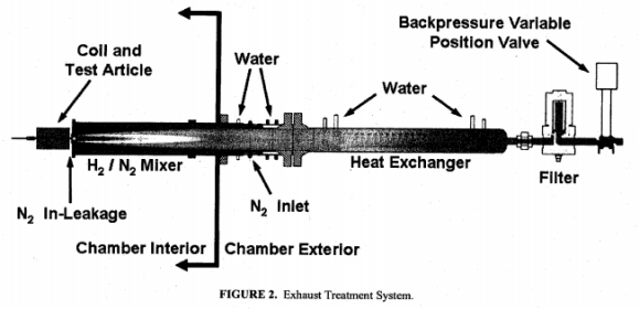
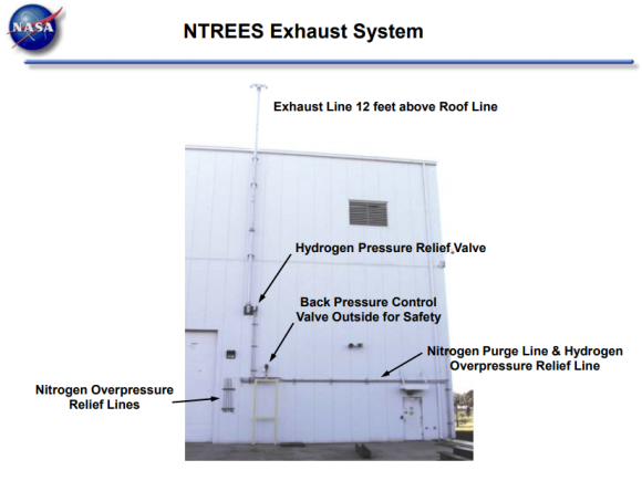
The mixer is also the first stage of the effluent cleanup system, designed to ensure that no potentially harmful chemical releases occur when the exhaust is released into the atmosphere. The second stage of the cleanup system is a water cooled sleeve that further chills the gas mixture (this system was upgraded in 2014 as well, to allow the system to carry away all the heat generated – and therefore be able to run longer-duration tests at higher temperatures). Finally, a filter and back-pressure system is used to clean the now-cool gas before it is exhausted through a smokestack on the outside of the facility.
After dilution, the gas stream passes in front of the aforementioned spectrometer. This device uses a laser to determine the elemental composition of the exhaust stream. Most spectrometers only examine a relatively small band, because they’re only needing to measure particular elements. In this case, the elements that could be in the exhaust stream besides the hydrogen and nitrogen include O (from decayed UO2), Ga (used to stabilize the UO2), Re (used to lower sintering temp requirements for the W), tungsten, and uranium, as well as any other trace elements used in the fuel element manufacture. These are spread fairly well across the periodic table, and as such a more versatile spectrometer was needed to be able to accurately assess the effluent stream.
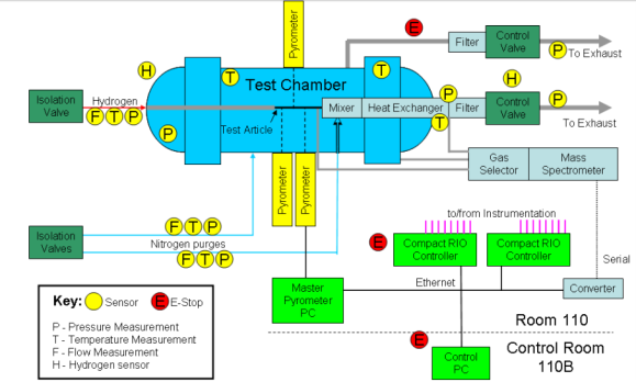
The data acquisition system consists of the mass spectrometer, pressure sensors (both GH2 and GN2), gas temperature sensors for both, flow sensors for both as well, thermocouples for general temperature measurements, H2 detectors in the chamber and the room, and pyrometers (black body radiation thermal detectors) to measure the temperature of the test article itself, and the associated electronics to collect the information from these sensors.
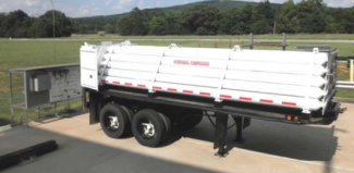
The design of the facility was safety-oriented from the beginning, with every precaution being taken to handle the GH2 safely. Some examples include: the GH2 storage is over 50 ft away from the building, and in the event of any failure, the supply (which is only on during a test) is shut off outside the building; all tubing on the inside of the building that can be welded, is welded; hydrogen sensors throughout the room, and the building NTREES is housed in; a nitrogen purge system to remove any air in the system; explosive sources were minimized and re-sited away from possible ignition sources; finally, the use of an automatic GH2 cutoff system with a strict set of shutdown parameters tied to either leaking hydrogen or high hydrogen level in the room, a loss of purge pressure or flow, potential failure in monitoring equipment, and finally the failure of the test article. A Class I, Division II Group B (hazardous) classification was obtained for the GH2 inlet manifold and main process pressure valve was obtained (and exceeded) to ensure that the facility is as safe as possible.
When put together, this facility allows for chemical and thermal testing of NTR fuel elements for extended periods of time in an environment that is missing only one component to mimic the environment of an NTR core: radiation. This means that fuel elements can be easily tested for manufacturing technique verification, clad material choice, erosion rates of fuel element materials, and other questions that are primarily chemical or mechanical rather than nuclear in origin.
There is one other difference between this test stand and the environment that a nuclear fuel element will, and that’s the source and distribution of the heat. In NTREES, the induction heating coil is the source of the heat, so it’s the hottest point in the pressure chamber. While the coil can be customized to a certain extent to manage the thermal load for different test articles, the spiral pattern will still be there, and the heat will be generated in the fuel element following the rules of inductive heating, not nuclear heating.
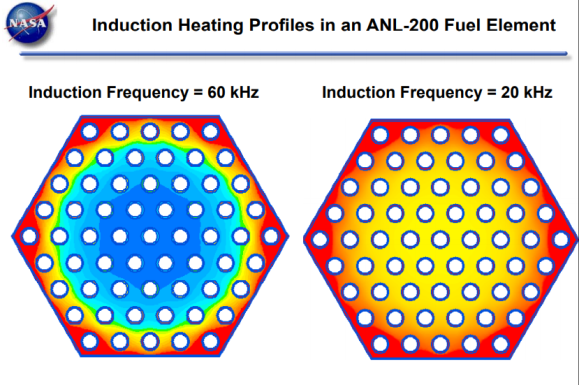
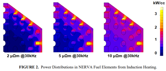
In a nuclear fuel element, considerable effort is taken to ensure that there is an even distribution of heat across the fuel element (taking into account all factors), because having a “hot spot” in your fuel element (higher-than desired density of fissile material) can do bad things to your reactor. Because of this, the power density is carefully assessed during manufacture and assembly. In the fuel element, temperature tends to peak around the edge of the fuel element, but otherwise be consistently distributed throughout. This difference can be significant, especially for clad/matrix interfaces where local hot spots can exacerbate thermal expansion differences and clad failure.
The radiation environment in a nuclear reactor will cause additional swelling (up to 9% in some CERMET fuels), and neutron damage, fission product buildup, and other effects will need to be accounted for as well. This difference is something that can be modeled, either through extrapolation from old data sets or from materials analysis in various radiation environments and beamlines in facilities around the world. While verification and validation tests in a reactor environment similar to an NTR core will be needed for whatever fuel elements are selected, this testing allows many of the hurdles to be addressed before this very expensive step is taken.
Testing Campaigns and Results Found
NTREES has now been in operation for over ten years, and has been used in a number of different testing campaigns. When first proposed, the focus was on the Small Nuclear Rocket Engine, a graphite-composite upgrade to the Pewee-class NTR proposed by Stan Borowski. The engine is best summarized in “How Small Is Big Enough?” The philosophy on this engine’s design was that a smaller engine was more easily ground-tested with the exhaust cleanup systems available at the time, and rather than going with a larger engine multiple engines could be used. This was an advanced graphite composite fuel element form, where the UO2 was layered through the graphite without clad during the deposition of carbon to build the graphite component of the fuel element, which leads to greater homogeneity (e.g. mixing) in the fuel element, but also adds complications from the fission product release side of things.
After the end of the SNRE program (although the design is still on the books – and assuming HEU becomes an option again remains, in many ways, the most mature NTR in the US design inventory, and the fallback if CERMET ends up not being a viable option for some reason), testing moved on to the Nuclear Cryogenic Propulsion Stage, or NCPS. This design is a CERMET-based reactor, based on the ANL-2000 CERMET FE. In many ways, this program parallels the ideas behind the Saturn N concept, with a nuclear upper stage to a heavy lift vehicle (in this case, the Space Launch System), although there are significant differences between the details of the design. This work continues today, and the engine is in the process of being converted from HEU to LEU use.
NTREES is also expected to be used with the LEU NTP program on the new BWXT LEU NTP design, which uses GE-711 fuel elements (fewer, wider bore propellant tubes than the ANL-2000). Due to the major changes in the design of the LEU NTP (See the second part of my LEU NTP blog series), there are many questions that need to be addressed, and even if we’re able to start doing hot-fire testing again NTREES will play a valuable role in pre-nuclear qualification and testing of solid-core NTR fuel elements until the money to maintain it runs dry.
Unique Capabilities, Difficulties, and Complications
NTREES was the first reusable facility of its’ type for thermal, non-nuclear NTR fuel element testing. Before, there were some tests using arc heating on CERMET FEs, but the early testing was mostly in-core testing of fuel elements (including the Nuclear Furnace 1 test), which shows not only the thermal and erosive effects but also the radiation effects. Since this has not been an option for decades, non-nuclear testing of various types has been conducted over the years, including the use of arc heating rather than induction heating. However, each of these test stands were one-off designs for a particular project, and often they weren’t able to handle a hydrogen-rich environment at all, much less a full-flow hydrogen test.
This doesn’t mean that NTREES is perfect. NTREES is a large facility, and one designed and certified to handle hazardous and explosive materials in bulk (mainly H2 and depleted uranium). In addition, the high H2 flow rate, and the temperatures involved, lead to this being an expensive facility to operate.
In addition, cooling the various components of the test stand has always been a major challenge, due to the temperatures that the test article must achieve. The 2014 upgrades led to improved water flow rate, but the N2 pump used to cool the sleeve of the gas mixer remained a limitation on testing duration. This is one example of many where in a complex system the actual limiting factor and the theoretical limiting factor are not the same.
To address some of these concerns, CFEET, or the CERMET Fuel Element Environmental Test stand, was constructed. You can read about that smaller, less-expensive test stand here.
Additional Reading and Sources:
NTREES Testing and Operation Status, Slideshow, Emrich NASA MSFC 2007
NTREES SNSF 2009 Slideshow, Schoenfeld NASA MSFC
Non-nuclear Testing of Space Nuclear Systems at NASA MSFC, Houts et al 2010
Modeling and Simulation of a Nuclear Fuel Element Test Section, Moran et al NASA MSFC 2011
Non-Nuclear Testing of Space Nuclear Systems at NASA MSFC, Houts et al 2011
NTREES Upgrade Activities, Conference Paper Emrich et al 2012
Non-nuclear Testing for NASA Fission Power System Technologies, NASA MSFC Fact Sheet, 2014
NTREES Phase II Upgrade Activities, Conference paper, Emrich et al 2013
NTREES Upgrade Activities, Slideshow Joint Propulsion Conference, 2013
NTREES Upgrade Activities, Conference Paper, Emrich NASA MSFC 2014
Initial Operation and Shakedown of NTREES, Conference Paper, NASA MSFC Emrich 2014
Hot Hydrogen Testing of W-UO2 CERMET Fuel Materials for NTP, Slideshow Hickman ea NASA MSFC 2014
Nuclear Cryogenic Propulsion Stage (NCPS) Testing with NTREES
NCPS Fuel Design and Fabrication, Presentation, Hickman et al NASA MSFC 2012
NASA’s Nuclear Thermal Propulsion Project, Conference Paper, Houts et al 2015
NASA’s Nuclear Thermal Propulsion Project, Slideshow Houts 2015
NASA’s Advanced Exploration Systems NTP Project, Presentation, Houts et al 2015
NASA’s Nuclear Thermal Propulsion Project, Slideshow Houts et al 2017
NCPS Fuel Element Testing in NTREES, NASA MSFC 2017
NCPS Fuel Element Testing in NTREES (different conference paper), Emrich NASA MSFC 2017
